


CRS-300 1:10 Redundancy Switch Revision 16
Ethernet Network Configurations MN/CRS300.IOM
3–3
3.3.2 Ethernet Redundancy with CRS-300
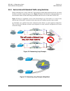
After the customer has determined the best configuration for near-to-far end Ethernet networks,
the CRS-300 1:10 Redundancy Switch may now be added to one or both ends of the link(s).
Ethernet redundancy using the CRS-300 can be accomplished using a wired-thru or
wired-around configuration.
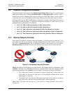
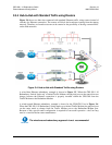
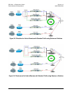
3.3.2.1 Wired-thru Connection
I
MPORTANT
This redundancy approach is the recommended and preferred
connection method.
The wired-thru Ethernet connection on the CRS-300 is the easiest and simplest choice for Ethernet
redundancy. This connection method – the same as used on the standard serial data interface –
provides a single connection for the User Data Interface and provides simple form-C relays that
route the Ethernet connection from the User connection to either the Traffic or Redundant Modem.
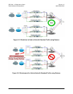
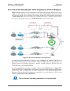
3.3.2.2 Wired-around Connection
I
MPORTANT
While this redundancy approach is not recommended, it can be used
after study of the LAN and WAN sides of the IP networks.
The wired-around Ethernet connection is used with the CRS-300 and the CDM-700 modem
where both modem data interface slots are needed; e.g., where one slot is HSSI or G.703 and the
other slot is GigE. With the Ethernet slot configured for the wired-around method, this gives full
redundancy capability to both data slots. However, care must be taken to ensure there are no
Ethernet network loops or connection problems – this method should only be used if both modem
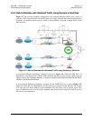
data slots are used. In general, the wired-around approach can be used in a hub-to-remotes
configuration with standard traffic.