


CRS-300 1:10 Redundancy Switch Revision 16
Modem, RMI/TMI, and Switch Configuration MN/CRS300.IOM
5–14
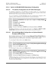
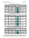
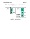
Table 5-5 illustrates the control signal configuration JP1 and JP2 jumper settings available on the
CRS-320 (obsolete) and CRS-340 TMIs:
Table 5-5. CRS-320/CRS-340 Jumper Settings
Jumper ‘JP1’
Jumper ‘JP2’
Control Signal Setting Jumpers Settings Control Signal Setting Jumpers Settings
RTS/CTS
Open Circuit
(TMI as-shipped)
None
DTR/DSR
Open Circuit
(TMI as-shipped)
None
RTS to CTS Loop
1 to 3
2 to 4
DTR to DSR Loop
1 to 3
2 to 4
TX IF
“User Mute Control”
Connects User DB-25 Pin
23 to Online Modem’s
“Tx_IF_Mute_L”:
0 = Mute = Tx_IF Off
1 = No Mute = Tx_IF On
3 to 5
Note: These jumper settings are available only on the following TMI versions:
For the CRS-320 (obsolete) – Rev. F. and later versions;
For the CRS-340 – Rev. D and later versions.