


CRS-300 1:10 Redundancy Switch Revision 16
Introduction MN/CRS300.IOM
1–15
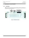
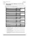
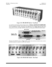
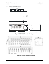
Figure 1-24. CRS-350 ESC Switch – Front Panel
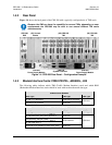
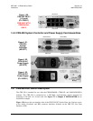
As explained in detail in the pertinent modem sections of
Chapter 5. CABLES AND CONNECTIONS,
the User’s equipment should be connected directly to the ports on the UDI instead of connecting directly
to the Traffic Modem’s “Audio”, “Overhead”, and “IDR Alarms” ports. Figure 1-25 shows the ty
pical
front panel for one of the (10) CRS-355 UDIs installed on the front panel of the CRS-350 ESC Switch.
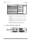
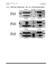
Figure 1-25.
CRS-355 UDI
DB-15 Female
DB-25 Male DB-9 Female
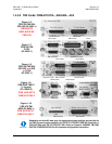
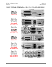
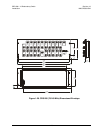
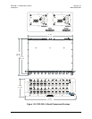
The back of the CRS-350, shown in Figure 1-26, contains the same three connectors that correlate
with their respective connectors on each of the modems.
Figure 1-26. CRS-350 ESC Switch – Rear Panel