


CRS-300 1:10 Redundancy Switch Revision 16
Cables and Connections MN/CRS300.IOM
4–28
Then, connect and secure the Control/Data Cable CA/WR0066 (for data purposes) between the
TMI(s) and Traffic CDM-625(s) as follows make all connections as follows:
• DB-25M connector labeled “P1” on the TMI(s), to
• DB-25F connector labeled “Data Interface” on the Traffic CDM-625(s).
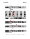
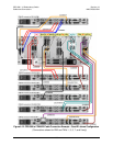
4.5.3.7 Quad E1 Data Connections
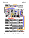
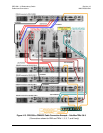
If Quad E1 is the driving traffic data type (refer to Figure 4-12 and Figure 4-13):
First,
connect the Control/Data Cable CA/WR0066 (for control purposes) between the Redundant
CDM-625 and the RMI (see
Sect. 4.5.3.1).
Next, connect and secure the Data ‘Y’ Cable CA-0000073 (DB-15F to <2X> DB-9M, 6’) between
the Redundant CDM-625 and the CRS-300 as follows:
• DB-15M connector labeled “P2” on the RMI, to
• DB-9F connector labeled “Balanced G.703” on the Redundant CDM-625 (using “P3”
connector on cable),
–and–
• DB-9F connector labeled “Aux G.703” on the Redundant CDM-625 (using “P2”
connector on cable).
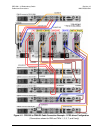
Then, connect and secure the Control Cable CA-0000069 (HD-15M to DB-9M, 6’) between the
CRS-365D TMI(s) and Traffic CDM-625(s) as follows:
• HD-15F connector labeled “J1” on the TMI(s), to
• DB-9F connector labeled “1:1 Control” on the Traffic CDM-625(s).
Finally, connect and secure a pair of Data Cables CA-0000136 (DB-9F to DB-9M, 6’) as
follows:
•
DB-9M connector labeled “P1” on the TMI(s), to
• DB-9F connector labeled “Aux G.703” on the Traffic CDM-625(s),
–and–
• DB-9M connector labeled “P2” on the TMI(s), to
• DB-9F connector labeled “Balanced G.703” on the Traffic CDM-625(s).