


CRS-300 1:10 Redundancy Switch Revision 16
Cables and Connections MN/CRS300.IOM
4–51
2. The Traffic CDM-700 must have the same interface cards in each slot as any of the other
Traffic CDM-700s have, or a blank panel installed.
3.
OC3 Optical TMI is not currently available.
4.
As of April 2007:
• CRS-336 TMI card replaces the CRS-335.
• CRS-306 RMI card replaces the CRS-305.
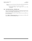
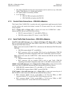
4.7.3 Control Cable Connections – CRS-300 to Modems
The Control Cable CA/WR12361-1 provides the serial communication path between the Switch
and the modems and controls the modem’s external Tx IF-mute control line, and is therefore
always required.
Refer to
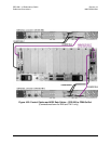
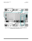
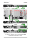
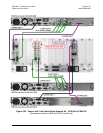
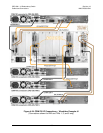
Figure 4-22 and Figure 4-23 to connect and secure the CA/WR12361-1 cables
between the CRS-300 and each CDM-700 as follows:
• HD-15F connector labeled “J1” on the RMI or TMI(s), to
• DB-15M connector labeled “P1 Alarms” on the CDM-700.
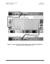
4.7.4 Serial Traffic Data Connections – CRS-300 to Modems
If G.703 is the traffic data type, refer to Figure 4-22, Figure 4-23, Figure 4-25, or Figure
4-27
to connect and secure the Traffic Data Cables CA/RF12278-1 and CA/RF12279-1 the CRS-
300 and each CDM-700 as follows:
First, connect and secure the CA/RF12279-1 cable between the Redundant CDM-700 and the
CRS-300:
• DB-15M connector labeled “P1” on the RMI, to
• BNC connectors (<4X> per installed CDI-10 card) on the Redundant CDM-700
(depending on the modem configuration, either <4X> or<8X> BNC connectors are used).
Next, connect and secure the CA/RF12278-1 cables between the CRS-300 and the Traffic
CDM-700(s):
• DB-9M connector labeled “P1” on the TMI(s), to
• BNC connectors (4X per installed CDI-10 card) on each Traffic CDM-700
(depending on the modem configuration, either <4X> or <8X> BNC connectors are used).
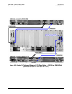
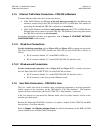
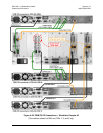
If HSSI is the traffic data type, refer to Figure 4-23 and Figure 4-26 to connect and secure the
HSSI Data Cable CA/WR9189-6 between the CRS-300 and each CDM-700 as follows:
• HSSI (HD-50F) connector labeled “J2” on the RMI, or “J3” on the TMI(s), to
• HSSI (HD-50F) connector labeled “HSSI” on each CDM-700.
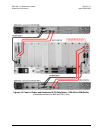
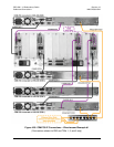
If OC3 copper is the traffic data type, refer to Figure 4-24 to connect and secure the pair of
BNC PL/0813-8 cables between the CRS-300 and each CDM-700 as follows:
• BNC connectors labeled "J4 Tx" on the RMI, or "J3 Tx"on the TMI(s), to BNC
connectors labeled "Tx" on the CDM-700's CDI-50 interface card, and
• BNC connectors labeled "J3 Rx" on the RMI, or "J5 Rx"on the TMI(s), to BNC
connectors labeled "Rx" on the CDM-700's CDI-50 interface card.