


CRS-300 1:10 Redundancy Switch Revision 16
Cables and Connections MN/CRS300.IOM
4–25
For specific details regarding the CA/WR0066 cable’s use as a TMI control and/or data cable,
refer to the data connection cabling instructions that follow for each driving traffic data type.
Additionally, when either the CRS-316, CRS-325, or CRS-336 TMI is used, the CA-0000069
(HD-15M to DB-9M, 6’) Control Cable is required between the installed TMI(s) and Traffic
CDM-625(s).
Refer to
Table 4-1 in Sect. 4.5.3 and to the data connection cabling instructions that follow for this
cable’s required use with the pertinent driving traffic data type.
4.5.3.2 G.703 Balanced / Unbalanced Data Connections
If G.703 (Balanced/Unbalanced) is the driving traffic data type, the means of interconnection
are dependant on the TMI used.
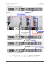
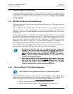
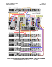
Figure 4-10 illustrates use of the CRS-330 and CRS-340 TMIs
with G.703, while
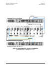
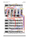
Figure 4-11 illustrates use of the CRS-325 TMI with G.703.
I
MPORTANT
TMIs used for G.703 traffic are not compatible with the CRS-365D TMI used for
Quad E1 traffic when used within the same CRS-300.
Make all connections according to the information that follows:
► When using the CRS-330 or CRS-340 TMIs (as shown in Figure 4-10):
First,
connect the Control/Data Cable CA/WR0066 (for control purposes) between the
Redundant CDM-625 and the RMI (see
Sect. 4.5.3.1).
Next, connect and secure the Control/Data Cable CA/WR0066 (for control purposes)
between the TMI(s) and Traffic CDM-625(s) as follows:
•
DB-25M connector labeled “P1” on the TMI(s), to
• DB-25F connector labeled “Data Interface” on the Traffic CDM-625(s).
Finally, connect and secure the Data Cable CA-0000072 (DB-15F to DB-9M, 6’), used for
either Balanced or Unbalanced G.703 data, between the RMI or TMI(s) and the Redundant
and Traffic CDM-625(s) as follows:
• DB-15M connector labeled “P2” on the RMI or TMI(s), to
• DB-9F connector labeled “Balanced G.703” on the Redundant and Traffic CDM-625(s).
► When using a CRS-325 TMI (as shown in Figure 4-11): Specific cabling requirements
apply for operation with the CDM-625.
First, connect the Control/Data Cable CA/WR0066 (for control purposes) between the
Redundant CDM-625 and the RMI (see
Sect. 4.5.3.1).
Next, connect and secure the Data Cable CA-0000072 (DB-15F to DB-9M, 6’), between the
Redundant CDM-625 and RMI as follows:
• DB-9F connector labeled “Balanced G.703” on the Redundant CDM-625, to
• DB-15M connector labeled “P2” on the RMI.
Then, connect and secure the Control Cable CA-0000069 (HD-15M to DB-9M, 6’) between
the TMI(s) and Traffic CDM-625(s) as follows:
• HD-15F connector labeled “J1” on the TMI(s), to