


CRS-300 1:10 Redundancy Switch Revision 16
Cables and Connections MN/CRS300.IOM
4–66
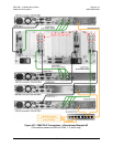
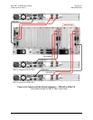
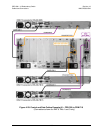
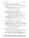
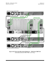
4.9 CDM-710G Modem Connections
If adding a modem to an operating 1:N system, care needs to be taken to not interfere with the
existing traffic. The cabling, power-up sequence and communication connections must be correct
to avoid contention in the system from the modem Tx carrier. This information is detailed in
Chapter 7.4.5 (CONFIG) ACTIVE MODEMS.
4.9.1 RMI/TMI Limitations and Considerations
I
MPORTANT
1. Traffic modems with differing data types are not supported by the Redundant
Modem. For example, the CRS-300 can not be populated with Traffic modems
with ASI and Traffic modes with HSSI.
2. Depending on the traffic data type, the appropriate jumper settings are
provided on the TMI to ensure proper operation for HSSI
with CA/TA signals
using the CRS-336 TMI. Refer to Chapter 4. MODEM, TMI, AND SWITCH
CONFIGURATION for this important configuration information
4.9.2 Interface Combinations
With (2) interface card slots available in the CDM-710G modem, there are several possible
interface card combinations.
Table 4-4 provides details for the CDM-710G interface card
combinations that are compatible with the CRS-300.
Table 4-4. CDM-710G Interface Card Combinations
CDM-710G Unit Configuration 1:N CRS-300 Configuration
Notes
Interface Slot 1 Interface Slot 2 TMI Card RMI Card
G.703 (CDI-10-1) None
CRS-325 CRS-306
-
G.703 (CDI-10-1) GigE (CDI-70)
Can be used as
Redundant Unit
HSSI (CDI-60) None
CRS-336
-
None GigE (CDI-70) CRS-306 -
HSSI (CDI-60) GigE (CDI-70)
Can be used as
Redundant Unit
Notes:
1. The Redundant Modem must have the same interface cards in each slot as any of the
Traffic Modems.
2.
The Traffic Modem must have the same interface cards in each slot as any of the other
Traffic Modems have, or a blank panel installed.
3.
Interface Slots 1 and 2 are not active simultaneously.