


CRS-300 1:10 Redundancy Switch Revision 16
Modem, RMI/TMI, and Switch Configuration MN/CRS300.IOM
5–16
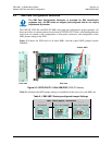
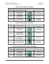
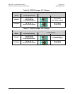
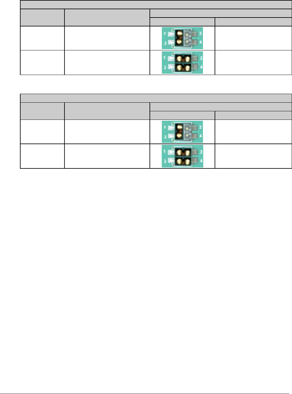
Table 5-6. CRS-336 Jumper ‘JP1’ Settings
User Interface Jumper ‘JP1’
Modem Control Signal Setting
Jumper Settings
Detail Pin Settings
CDM-625
TA_A to CA_A
Loop Connected
at User HSSI Connector
Pin 1 to Pin 3
(Note: TMI as shipped)
SLM-5650A
TA_A & CA_A
Routed to online modem
Pin 1 to Pin 2;
Pin 3 to Pin 4
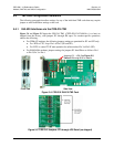
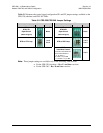
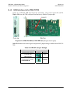
Table 5-7. CRS-336 Jumper ‘JP2’ Settings
User Interface Jumper ‘JP2’
Modem Control Signal Setting
Jumper Settings
Detail Pin Settings
CDM-625
TA_B to CA_B
Loop Connected
at User HSSI Connector
Pin 1 to Pin 3
(Note: TMI as shipped)
SLM-5650A
TA_B & CA_B
Routed to online modem
Pin 1 to Pin 2;
Pin 3 to Pin 4