


A-1
Appendix A. CABLE DRAWINGS
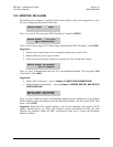
A.1 Introduction
This appendix contains drawings of cables used with the CRS-300. These cables are divided into three categories: User / Utility Cables,
Control Cables, and Control / IF / Data Cables. Each section includes illustrations of the cables’ technical specifications; additionally, the
tables provided in Sections A.3 and A.4 cross-reference cabling illustrations included in
Chapter 4. CABLES AND CONNECTIONS.
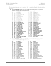
A.2 User/Utility Cables
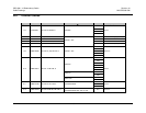
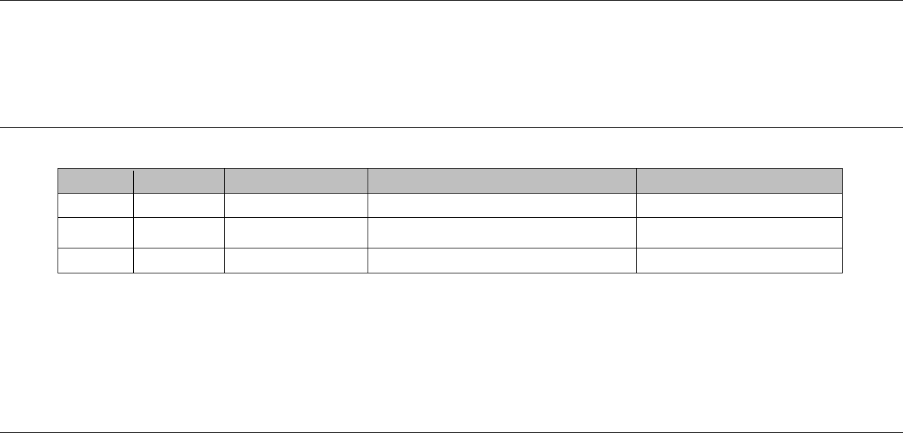
App. A FIG CEFD P/N DESCRIPTION
USED WITH CRS-300 Æ …
USED FOR (DATA TYPE)
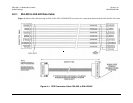
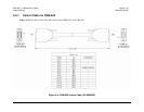
A-1 N/A DB-25M Æ DB-37F User data EIA-530 Æ EIA-422/449 DCE Conversion
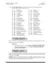
A-2 N/A
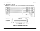
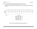
DB-25M Æ 34-pin
Winchester (Female)
User data EIA-530 Æ V.35 DCE Conversion
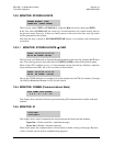
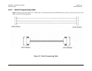
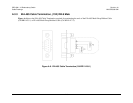
A-3 N/A DB-9M Æ DB-9F User EIA-232 Switch Programming / Flash Upgrade CRS-300 Remote Æ PC Serial Port