


CRS-300 1:10 Redundancy Switch Revision 16
Connector Pinouts MN/CRS300.IOM
6–7
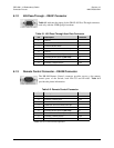
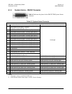
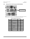
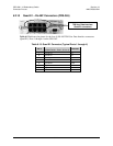
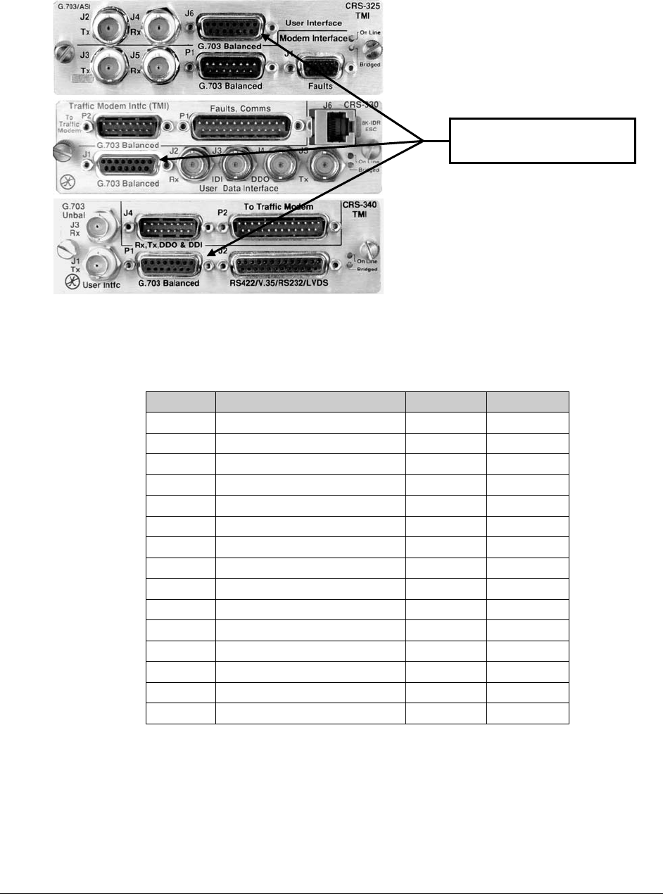
6.2.5 Balanced G.703 – DB-15F Connector (CRS-325/330/340)
Table 6-8
indicates the pinout for the DB-15F TMI User Data
Interface connector (Balanced
G.703): Located at J6 on the CRS-325; J1 on the CRS-330; and P1 on the CRS-340.
Table 6-8. Balanced G.703 Connector
Pin Signal Description Name Direction
1* Tx, Drop Data Input (-) DDI– In
9* Tx, Drop Data Input (+) DDI+ In
2 Ground GND
10 Not Used
3* Rx, Insert Data Output (-) IDO– Out
11* Rx, Insert Data Output (+) IDO+ Out
4 Ground GND
12 Drop Data Output (-) DDO– Out
5 Drop Data Output (+) DDO+ Out
13 Insert Data Input (-) IDI– In
6 Insert Data Input (+) IDI+ In
14 Not Used
7 Not Used
15 Not Used
8 Not Used
* Use for all non-Drop and Insert and T2/E2 balanced applications.
TMI User Data Interface:
Balanced G.703 connector