


4–1
Chapter 4.
CABLES AND CONNECTIONS
4.1 Overview
All cables for connecting the CRS-300 1:10 Redundancy Switch to the modems or within the system
are available from Comtech EF Data. These cables can be ordered at the same time the order is placed
for the CRS-300.
If fabricated by the customer, the cables required between each modem and Switch plug-in RMI
or TMI card should be of shielded, twisted-pair construction, with the grounded shield bonded to
the back shell. All data cables should be wired correctly using the pinout and connection
information as specified in
Appendix A. CABLE DRAWINGS.
IMPORTAN
T
Leave the Switch and all modems powered off until all connections are ready.
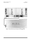
Once the Switch and all the modems have been mounted, the User must properly attach all required
cabling. In most cases the modem accepts the male end of the cable, while connectors on the RMI or
TMI card accepts the female end of the cable in the section of the card labeled “Modem Interface.”
Refer to the subsections in
Chapter 1.4 Description of CRS-300 Features for detailed information
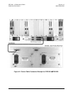
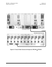
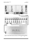
on these interfaces. Illustrations featured throughout this chapter provide cabling configuration
examples for RMI or TMI interfaces – i.e., the interconnection of a Redundant Modem to a Switch
RMI card, or the interconnection between a Switch TMI card and a Traffic Modem. The
step-by-step process for connecting a variety of Switch and modem configurations is outlined in the
following chapter sections:
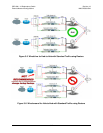
• Sect. 4.2 Switch-to-Switch Connections
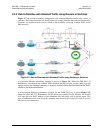
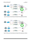
• Sect. 4.3 CDM-570/570L Modem Connections
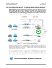
• Sect. 4.4 CDM-600/600L Modem Connections
• Sect. 4.5 CDM-625 Modem Connections
• Sect. 4.6 CDM-Qx/QxL Modem Connections
• Sect. 4.7 CDM-700 Modem Connections
• Sect. 4.8 CDM-710 Modem Connections
• Sect. 4.9 CDM-710G Modem Connections
• Sect. 4.10 SLM-5650/5650A Modem Connections
• Sect. 4.11 IF Cable Connections