


CRS-300 1:10 Redundancy Switch Revision 16
Modem, RMI/TMI, and Switch Configuration MN/CRS300.IOM
5–10
5.3 RMI Card Configuration Reference
IMPORTANT
The RMI Card Confi
g
uration Reference is provided for RMI identification
purposes only. All RMI cards are shipped pre-confi
g
ured and do not requir
e
adjustments by the user.
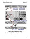
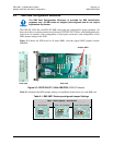
The CRS-305, CRS-306, and CRS-307 RMI cards come pre-configured for proper operation. All
three cards share a common printed circuit board (CEFD P/N PC/11494x); what distinguishes the
cards from one another is the configuration of front panel connectors, and configuration of the
JMP1 jumper setting on the PCB.
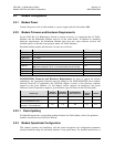
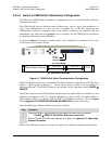
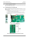
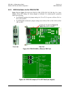
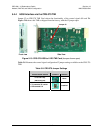
Figure 5-3 shows the PCB used for all three RMIs, with the typical JMP1 jumper location
identified.
Figure 5-3. CEFD P/N PC/11494x RMI PCB (CRS-307 shown)
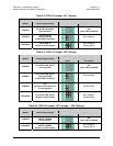
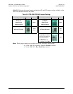
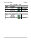
Table 5-1 illustrates the JMP1 jumper settings, as established at the factory for each RMI card.
Table 5-1. RMI JMP1 Factory-configured Jumper Settings
‘JMP1’ Jumper Setting
–
A
S SHIPPED
CRS-305
(No jumpers)
CRS-306
(Pins 1 to 2 jumped)
CRS-307
(Pins 3 to 4 jumped)
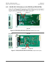
Jumpe
r
JMP1
Front view Side view