


CRS-300 1:10 Redundancy Switch Revision 16
Introduction MN/CRS300.IOM
1–5
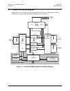
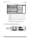
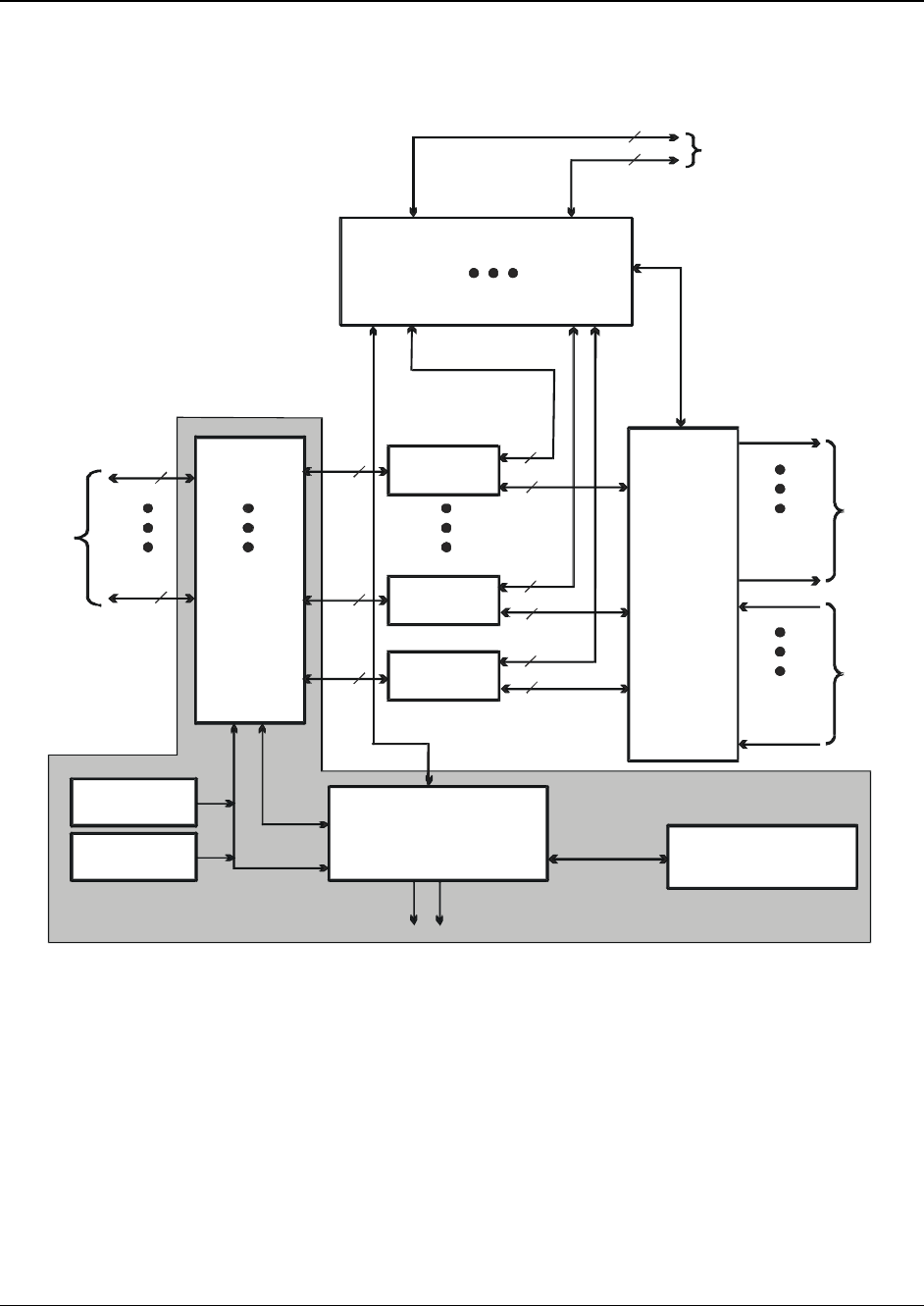
1.3 System-Level Block Diagram
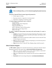
Figure 1-1 shows the system-level block diagram of the CRS-300 1:10 Redundancy Switch,
including the optional CRS-280/280L IF and CRS-350 ESC Switches.
Figure 1-1. Typical Redundancy System-Level Block Diagram
CRS-240
Power Suppl
y
CRS-240
Power Suppl
y
CRS-230
System Controlle
r
Control
System Alarms
CRS-300
Front Panel Keypad,
LCD and LED Displa
y
RMI Interface
CRS-280/280L
IF Switch
(Optional)
See Fig. 1-2
for schematic
Use
r
Terrestrial
Data
To Up
Converters
Modem # 1
Modem # 10
Modem #11
From Down
Converters
CRS-350 ESC Switch
(Optional)
TMI #10
TMI #1
RMI
Control
CRS-300 Data Switch
2
3
1 or 2
3
2
2
3
3
3
1 or 2
1 or 2
1 or 2
1 or 2
User Alarms,
Audio,
Overhead
RMI
TMI
#1
TMI
#10
User EIA-232/485 M&C