


CRS-300 1:10 Redundancy Switch Revision 16
Connector Pinouts MN/CRS300.IOM
6–6
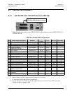
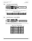
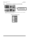
6.2.3 ASI – BNC Connectors (CRS-325)
Table 6-6 indicates the TMI User Data I
nterface BNC connectors (ASI) on the CRS-325.
Table 6-6. ASI Connectors
BNC Connector TMI CRS-325 Ref Des Description Direction
Tx J2 Tx, ASI In
Rx J4 Rx, ASI Out
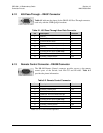
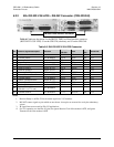
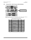
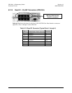
6.2.4 8 kHz IDR Connector – RJ-45F (CRS-330)
Table 6-7 indicates the RJ-45F connector on the CRS-330 TMI tha
t serves as the user interface to the
EIA-422 clock and data for the 8 kHz IDR Engineering Service Channel.
Table 6-7. 8 kHz – IDR ESC Connector
Pin # Signal Function Name Direction
1 Tx Data+ SD+ In
2 Tx Data- SD- In
3 Rx Data+ RD+ Out
4 Tx Clock+ ST+ Out
5 Tx Clock- ST- Out
6 Rx Data- RD- Out
7 Rx Clock+ RT+ Out
8 Rx Clock- RT- Out
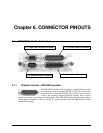
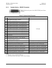
User Clock/Data Interface:
IDR ESC Interface connector
TMI User Data Interface:
ASI connectors