


CRS-300 1:10 Redundancy Switch Revision 16
Introduction MN/CRS300.IOM
1–14
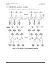
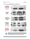
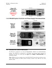
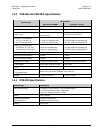
1.4.5 CRS-300 System Controller and Power Supply Card Assemblies
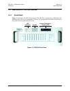
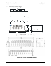
Figure 1-21.
CRS-230
System
Controller
(AS/0377)
DB-9 Female DB-25 Male
DB-9 Male DB-25 Female
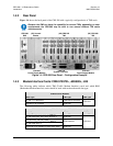
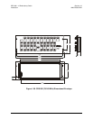
Figure 1-22.
CRS-240 AC
Power Supply
(AS/0376)
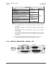
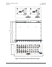
Figure 1-23.
CRS-250 DC
Power Supply
(PL/10458-1)
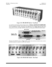
1.5 CRS-350 ESC Switch Description
The CRS-350 is intended for use with the CDM-600/600L, CDM-625, and SLM-5650/5650A
modems. The CRS-350 is constructed as a 3RU-high, rack-mounting chassis designed for
mounting to the back of a 19-inch rack. See Figure 2-1 in
Chapter 2. INSTALLATION for an
installation example.
Figure 1-24
shows the user interface si
de of the CRS-350 ESC Switch. Here, the User has access
to the Audio, Overhead, and IRD connector interfaces featured on the CRS-355 User Data
Interface (UDI).
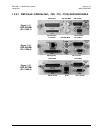
Figure 1-20.
CRS-365 TMI E1
(1-4 ports)
(PL/12985-1)
FOR USE WITH
CDM-Qx/QxL
ONLY
(4X) RJ-45
(4X) RJ-45 HD-15 Female