


CRS-300 1:10 Redundancy Switch Revision 16
Cables and Connections MN/CRS300.IOM
4–43
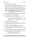
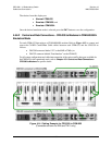
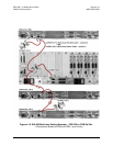
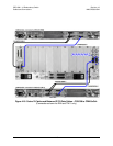
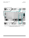
Next, connect and secure the (4X) Quad E1 TMI Data Cables (CEFD P/N PP/CAT5FF7FTGY)
as follows:
• RJ-48 connectors labeled “Port 1” through “4” on the TMI(s), to
• RJ-48 connectors labeled “Port 1” through “Port 4” on the Traffic
CDM-Qx/QxL.
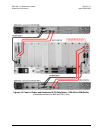
4.6.5 User Data Connections – CRS-300 to User
The User’s traffic data from multiplexing equipment or a test data generator should connect to the
connectors on the TMI labeled “User Data Interface”. This interface replaces the direct
connection to the Traffic Modem’s “Data Interface” connectors.
Because the Redundant Modem’s function is to replace a faulted traffic modem, the RMI does not
have a User Data Interface.
Refer to
Chapter 1.4.4 Modem Interface Cards for detailed information on the RMI and TMI
cards available for use with the CDM-Qx/QxL modems.