


CRS-300 1:10 Redundancy Switch Revision 16
Cables and Connections MN/CRS300.IOM
4–12
4.3 CDM-570/570L Modem Connections
If adding a modem to an operating 1:N system, care needs to be taken to not interfere with the
existing Traffic Modem. The cabling, power-up sequence must be correct to avoid contention in
the system from the modem Tx carrier. This sequence is detailed in
Chapter 7.4.5 (CONFIG)
ACTIVE MODEMS
.
I
MPORTANT
Traffic modems with differing data types can all be supported by the Redundant
Modem.
4.3.1 Control and Data Connections – CRS-300 to Modems
The 25-pin Control/Data Cable CA/WR0066 provides the EIA-422/232 traffic data path and
serial communication path between the Switch and the modems, and is therefore always required
even if the data type is G.703.
I
MPORTANT
Depending on the traffic data type, the appropriate jumper settings are provided
on the TMI to ensure proper operation for EIA-422
with RTS/CTS, DTR/DSR signal
using the CRS-320 (obsolete) or CRS-340 TMI. Refer to Chapter 4. MODEM, TMI,
AND SWITCH CONFIGURATION for this important configuration information.
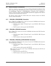
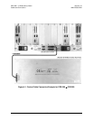
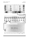
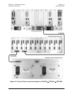
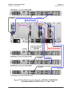
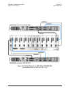
Refer to Figure 4-6 to connect and secure the CA/WR0066 cables between each CDM-570/570L
and the CRS-300 as follows:
• DB-25M connector labeled “P1” on the RMI or TMI(s), to
• DB-25F connectors labeled “Data Interface” on the CDM-570/570Ls.
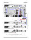
If G.703 is the traffic data type, also connect and secure the Data Cable CA/WR11999-6, used
for either Balanced or Unbalanced G.703 data, as follows:
• DB-15M connector labeled “P2” on the RMI or TMI(s), to
• DB-15F connectors labeled “Balanced E1/T1” on the CDM-570/570Ls.
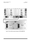
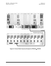
4.3.2 User Data Connections – CRS-300 to User
The User’s traffic data from multiplexing equipment or a test data generator should connect to the
connectors labeled “User Data Interface” on the TMI(s). This interface replaces the direct
connection to the Traffic Modem’s “Data Interface” connectors.
I
MPORTANT
1. Because the Redundant Modem’s function is to replace a faulted
Traffic Modem, the RMI does not have a User Data Interface.
2. Ensure that the correct operation for Balanced or Unbalanced G.703
data is configured on the modem.
For T1/E1 operation, the optional CN-0000268 T1/E1 Adapter (illustrated in Figure A-32 in
Appendix A. CABLE DRAWINGS) may be purchased from Comtech EF Data to adapt the
Balanced G.703 DB-15F connector on the User data side of the TMI to a RJ-48 female connection.