


CRS-300 1:10 Redundancy Switch Revision 16
Connector Pinouts MN/CRS300.IOM
6–5
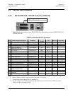
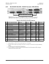
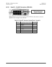
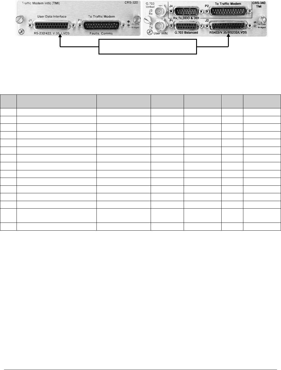
6.2.2 EIA-232/422/V.35/LVDS – DB-25F Connector (CRS-320/340)
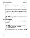
Table 6-5 in
d
icates the pinout for the DB-25F TMI User Data Interface connector
(RS232/422/V.35/LVDS): J1 on the CRS-320 (obsolete), and J2 on the CRS-340.
Table 6-5. EIA-232/422/V.35/LVDS Connector
Pin Generic Signal Description Direction
EIA-422/
RS 530
V.35
EIA-
232
Circuit No.
1 Shield - Shield FG AA 101
2 Transmit Data A DTE to Modem SD A SD A BA 103
3 Receive Data A Modem to DTE RD A RD A BB 104
7 Signal Ground - SG SG AB 102
8 Receiver Ready A Modem to DTE RR A RLSD * CF 109
9 Receive Clock B Modem to DTE RT B SCR B - 115
10 Receiver Ready B Modem to DTE RR B - 109
11 Transmit Clock B DTE to Modem TT B SCTE B - 113
12 Internal Transmit Clock B Modem to DTE ST B SCT B - 114
14 Transmit Data B DTE to Modem SD B SD B - 103
15 Internal Transmit Clock A Modem to DTE ST A SCT A DB 114
16 Receive Data B Modem to DTE RD B RD B - 104
17 Receive Clock A Modem to DTE RT A SCR A DD 115
23
External Carrier Off
(EIA-232 ‘1' or TTL ‘low’)
DTE to Modem - - - -
24 Transmit Clock A DTE to Modem TT A SCTE A DA 113
Notes:
1. Receiver-Ready is an EIA-232-level control signal on a V.35 interface.
2. DO NOT connect signals to pins which are not shown - these pins are reserved for use by the redundancy
system.
3. 'B' signal lines are not used for EIA-232 applications.
4. For X.21 operation, use the EIA-422 pins, but ignore Receive Clock if the modem is DTE, and ignore
Transmit clocks if the modem is DCE.
TMI User Data Interface connector