


CRS-300 1:10 Redundancy Switch Revision 16
Cables and Connections MN/CRS300.IOM
4–73
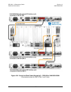
• HSSI (HD-50F) connector labeled “J2” on the RMI or “J3” on the TMI(s), to
• HSSI (HD-50F) connector labeled “J7 HSSI” on the SLM-5650/5650A.
If EIA-530/-232 is the traffic data type, connect and secure the Control/Data Cable CA/WR0066
(used for data purposes) between the CRS-300 and each SLM-5650/5650A as follows:
• DB-25M connector labeled “P2” on the RMI, or “P1” on the TMI(s), to
• DB-25F connector labeled “J6 EIA530” on the SLM-5650/5650A.
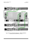
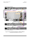
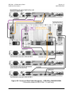
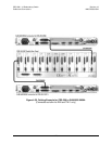
Referring to Figure 4-33:
If Balanced G.703 is the traffic data type
, connect and secure the CA/WR9038-1 cable between
the CRS-300 and each SLM-5650/5650A as follows:
• DB-15M connector labeled “P1” on the RMI or TMI(s), to
• DB-15F connector labeled “J1 Bal Data” on the SLM-5650/5650A.
If Unbalanced G.703 is the traffic data type, connect and secure the pair of BNC PL/0813-8
cables between the CRS-300 and each SLM-5650/5650A as follows:
• BNC connectors labeled “J4 Tx” on the RMI, or “J3 Tx” on the TMI(s), to BNC
connectors labeled “J3 Rx” on the SLM-5650/5650A, and
• BNC connectors labeled “J3 Rx” on the RMI, or “J5 Rx” on the TMI(s), to BNC
connectors labeled “J2 Tx” on the SLM-5650/5650A.
4.10.3.1 Ethernet Traffic Data Connections
Due to limitations of its backplane, the CRS-300 can support Single-port Ethernet Bridge
Mode
only.
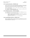
4.10.3.1.1 Ethernet Bridge Mode via the Optional GbE Interface
When the SLM-5650/5650A modems are equipped with the optional single-port 10/100/1000
Base-T (GbE) Interface card, only
Single-port Ethernet Bridge Mode is possible. As shown in
Figure 4-32, connect and secure all Cat5 Data Cables PP/CAT5FF3FTGY as follows:
• RJ-45 connector labeled “J5” on the RMI or TMI, to
• RJ-45 connector labeled “J1” on the optional GbE Interface card.
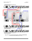
4.10.3.1.2 Ethernet Bridge Mode via the Optional NP Interface
When the SLM-5650/5650A modems are equipped with the optional multi-port Network
Processor (NP) Interface card, only
Single-port Ethernet Bridge Mode is possible. As shown in
Figure 4-34, connect and secure all Cat5 Data Cables PP/CAT5FF3FTGY as follows:
• RJ-45 connector labeled “Port 1” on the RMI or TMI, to
• RJ-45 connector labeled “Port 1” on the optional Network Processor (NP) Interface card.
IMPORTANT
Do not connect to Port 2 through Port 4 on the RMI, TMI, or optional
Network Processor (NP) Interface when operating in Single-port
Ethernet Bridge Mode.