


CRS-300 1:10 Redundancy Switch Revision 16
Cables and Connections MN/CRS300.IOM
4–36
The choices from this display are:
• Normal: CDM-625
• Emulate: CDM-600
, and
• Emulate: CDM-600L.
Once the desired emulation mode is selected, press the
ENT button to save the configuration.
4.5.6.2 Control and Data Connections – CRS-300 to Modems in CDM-600/600L
Emulation Mode
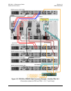
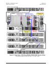
For each CDM-625 that replaces a CDM-600/600L modem: Refer to Figure 4-15 to connect and
secure the CA/WR Control/Data Cable cables between each CDM-625 and the CRS-300 as
follows:
• DB-25M connector labeled “P1” on the RMI or TMI(s), to
• DB-25F connector labeled “Data Interface” on the CDM-625.
For all system configurations and cable interconnection of the various traffic data types available for
the CDM-625 in this operational mode, refer to
Chapter 4.5.1 Control and Data Connections –
CRS-300 to Modems
for specific details.
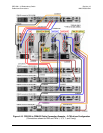
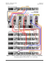
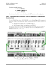
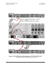
Figure 4-14. Cabling Example for CRS-350 to CDM-625
(Connections shown for RMI and TMI 1 only)