


© National Instruments Corporation
2-1 PC-DIO-96 User Manual
Chapter 2
Configuration and Installation
This chapter describes the PC-DIO-96 jumper configurations, installing the PC-DIO-96 board in
your computer, signal connections to the PC-DIO-96 board, and cabling instructions.
Board Configuration
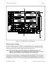
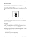
The PC-DIO-96 contains one DIP switch and one jumper to configure the base I/O address and
interrupts, respectively. The DIP switch and jumper are shown in the parts locator diagram in
Figure 2-1.
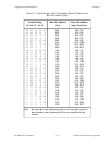
The PC-DIO-96 is configured at the factory to a base I/O address of hex 180 and to interrupt
level 5. These settings (shown in Table 2-1) are suitable for most systems. However, if your
system has other hardware at this base I/O address or interrupt level, you need to change these
settings on the PC-DIO-96 (as described in the following pages) or on the other hardware.
Record your settings in the PC-DIO-96 Hardware and Software Configuration Form in
Appendix D, Customer Communication.
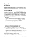
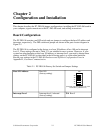
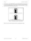
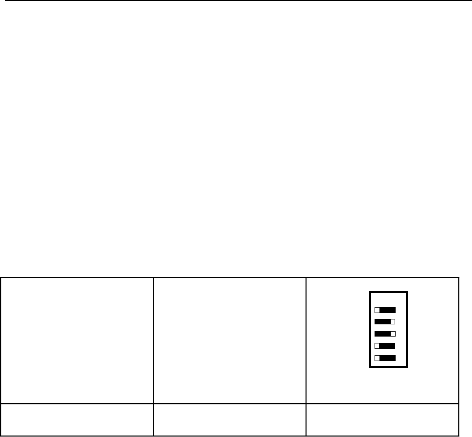
Table 2-1. PC-DIO-96 Factory-Set Switch and Jumper Settings
Base I/O Address Hex 180
(factory setting)
1
2
3 4 5
A9
A8
A7
A6
A5
U26
(The black side indicates the side of the
switch that is pushed down.)
Interrupt Level Interrupt level 5 selected
(factory setting)
W1: Row 5