


Register-Level Programming Chapter 4
PC-DIO-96 User Manual 4-8 © National Instruments Corporation
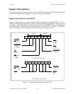
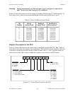
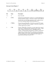
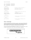
Interrupt Control Register 2
D7 D6 D5 D4 D3 D2 D1 D0
X X X X X INTEN CTRIRQ CTR1
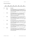
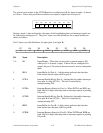
Bit Name Description
7–3 X Don’t Care Bit.
2 INTEN Global Interrupt Enable Bit—If this bit is set, the PC-DIO-96 can
interrupt the host computer. If this bit is cleared, the PC-DIO-96
interrupt line is put into high-impedance mode, so other devices
can use the interrupt channel selected by jumper W1.
1 CTRIRQ Counter Interrupt Enable Bit—If this bit is set, the 8253 counter
outputs can interrupt the host computer. If this bit is cleared, the
counter outputs have no effect.
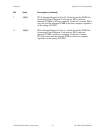
0 CTR1 Counter 1 Enable Bit—If this bit is set, the output from counter 1
of the 8253 is connected to the interrupt request circuitry. In this
mode, counter 0 of the 8253 acts as a frequency scaler for
counter 1, which generates the interrupt. If CTR1 is cleared, the
output from counter 0 of the 8253 is connected to the interrupt
request circuitry. In this mode, counter 0 generates the interrupt.
For more information, see the section later in this chapter on
programming interrupts using the 8253.