


© National Instruments Corporation
3-1 PC-DIO-96 User Manual
Chapter 3
Theory of Operation
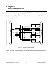
This chapter contains a functional overview of the PC-DIO-96 board and explains the operation
of each functional unit making up the PC-DIO-96.
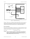
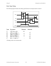
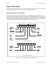
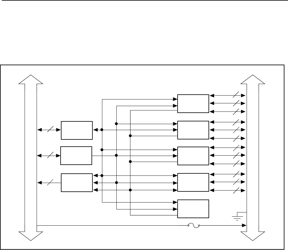
The block diagram in Figure 3-1 illustrates the key functional components of the PC-DIO-96
board.
8
21
6
+5 VDC
8
8
8
8
8
8
8
8
8
8
8
8
Data
Transceiver
PC I/O
Channel
Control
Interrupt
Control
Circuitry
Port A
Port B
Port C
I/O Connector
PC I/O Channel
OKI
82C55A PPI
OKI
82C55A PPI
OKI
82C55A PPI
OKI
82C55A PPI
AMD
8253 Timer
1 A Fuse
Port A
Port A
Port A
Port B
Port B
Port B
Port C
Port C
Port C
Figure 3-1. PC-DIO-96 Block Diagram
The PC I/O channel consists of an address bus, a data bus, interrupt lines, and several control and
support signals.