


Register-Level Programming Chapter 4
PC-DIO-96 User Manual 4-22 © National Instruments Corporation
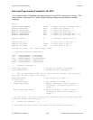
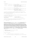
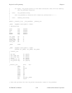
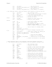
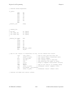
Interrupt Programming Example for the 8253
An in-depth example of handling interrupts generated by the 8253 is presented as follows. The
main program is presented in C, while sample interrupt routines are presented in assembly
language.
Main() {
#define BASE_ADDRESS 0x180 /* Board located at address 180 */
#define CTR0offset 0x10 /* Offset for counter 0 */
#define CTR1offset 0x11 /* Offset for counter 1 */
#define CTRCNFGoffset 0x13 /* Offset for 8253 CNFG */
#define IREG1offset 0x14 /* Offset for Interrupt Reg. 1 */
#define IREG2offset 0x15 /* Offset for Interrupt Reg. 2 */
#define channel 5 /* Interrupt channel on W1 */
#define use_ctr1 0 /* 0 for ctr0, 1 for ctr1 */
#define ctr0_data 10000 /* Pulse every 5 msec */
#define ctr1_data 1000 /* Pulse every 5 sec */
unsigned int ctr0, ctr1, cnfg, ireg1, ireg2;
/* Calculate register addresses */
ctr0 = BASE_ADDRESS + CTR0offset;
ctr1 = BASE_ADDRESS + CTR1offset;
cnfg = BASE_ADDRESS + CTRCNFGoffset;
ireg1 = BASE_ADDRESS + IREG1offset;
ireg2 = BASE_ADDRESS + IREG2offset;
/* Disable interrupts */
outp(ireg1,0x00); /* Disable all 82C55A interrupts */
outp(ireg2,0x00); /* Disable counter interrupts */
/* Set up the counter modes--do not write out the counter load values at
this time, as this starts the counter. */
outp(cnfg,0x34); /* Set counter 0 to mode 2 */
if (use_ctr1) {
outp(cnfg,0x74); /* Set counter 1 to mode 2 */
outp(ireg2,0x07); /* Enable interrupts, enable counter
interrupts, and select counter 1's
output */
}
else outp(ireg2, 0x06); /* Enable interrupts, enable counter
interrupts, and select counter 0's
output */
/* At this point, you should install your interrupt service routine using the
interrupt channel selected by W1. */
/* install_isr(channel,...); */
/* Now write out the counter load values for the selected counters. */