


Configuration and Installation Chapter 2
PC-DIO-96 User Manual 2-2 © National Instruments Corporation
W1
U26
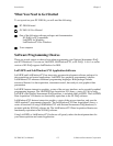
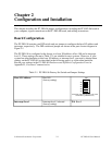
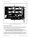
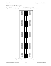
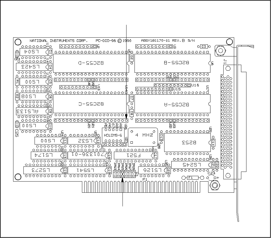
Figure 2-1. PC-DIO-96 Parts Locator Diagram
Base I/O Address Settings
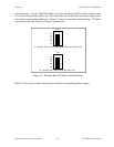
The base I/O address for the PC-DIO-96 is determined by the switches at position U26 (see
Figure 2-1). The switches are set at the factory for the I/O address hex 180. With this default
setting, the PC-DIO-96 uses the I/O address space hex 180 through 19F.
Note: Verify that this space is not already used by other equipment installed in your
computer. If any equipment in your computer uses this I/O address space, you must
change the base I/O address for the PC-DIO-96 or for the other device.
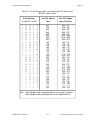
Each switch in U26 corresponds to one of the address lines A9 through A5. Thus, the range for
possible base I/O address settings is hex 000 through 3E0. Base I/O address values hex 000
through 0FF are reserved for system use. Base I/O values hex 100 through 3FF are available on
the I/O channel. A4, A3, A2, A1, and A0 are used by the PC-DIO-96 to decode accesses to the