


Register-Level Programming Chapter 4
PC-DIO-96 User Manual 4-18 © National Instruments Corporation
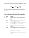
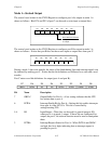
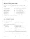
Port C status-word bit definitions for bidirectional data path (port A only):
D7 D6 D5 D4 D3 D2 D1 D0
OBFA* INTE1 IBFA INTE2 INTRA I/O I/O I/O
Bit Name Description
7 OBFA* Output Buffer for Port A—A low setting indicates that the CPU
has written data to port A.
6 INTE1 Interrupt Enable Bit for Port A Output Interrupts—Setting this bit
enables output interrupts from port A of the 82C55A. This bit is
controlled by setting/resetting PC6.
5 IBFA Input Buffer for Port A—A high setting indicates that data has
been loaded into the input latch of port A.
4 INTE2 Interrupt Enable Bit for Port A Input Interrupts—Setting this bit
enables input interrupts from port A of the 82C55A. This bit is
controlled by setting/resetting PC4.
3 INTRA Interrupt Request Status for Port A—If INTE1 and IBFA are high,
then this bit is high, indicating that an interrupt request is pending
for port A input transfers. If INTE2 and OBFA* are high, then this
bit is high, indicating that an interrupt request is pending for port A
output transfers.
2–0 I/O Input/Output—These bits can be used for general-purpose I/O lines
if group B is configured for mode 0. If group B is configured for
mode 1, refer to the bit explanations shown in the preceding mode
1 sections.
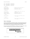
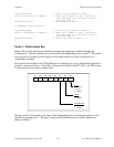
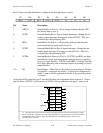
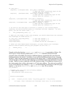
At the digital I/O connector, port C has the following pin assignments when in mode 2. Notice
that the status of STBA* and the status of ACKA* are not included in the port C status word.
PC7
PC6
PC5
PC4
PC3
PC2
PC1
PC0
OBFA*
ACKA*
IBFA
STBA*
INTRA
#
#
#
Group A
Group B
# The three port C lines associated with group B function based on the mode selected for group B;
that is, if group B is configured for mode 0, PC2-PC0 function as general-purpose I/O, but if group B is
configured for mode 1 input or output, PC2-PC0 function as handshaking lines as shown in the
preceding mode 1 sections.