


Register-Level Programming Chapter 4
PC-DIO-96 User Manual 4-16 © National Instruments Corporation
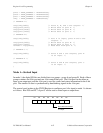
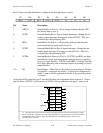
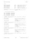
Bit Name Description (continued)
2 INTEB Interrupt Enable Bit for Port B—Setting this bit enables interrupts
from port B of the 82C55A. This bit is controlled by
setting/resetting PC2.
1 OBFB* Output Buffer for Port B—A low setting indicates that the CPU
has written data to port B.
0 INTRB Interrupt Request Status for Port B—When INTEB and OBFB* are
high, this bit is high, indicating that an interrupt request is pending
for port B.
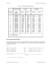
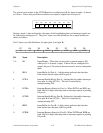
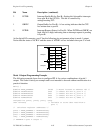
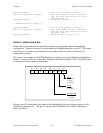
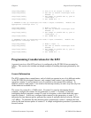
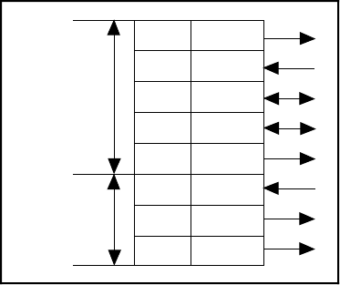
At the digital I/O connector, port C has the following pin assignments when in mode 1 output.
Notice that the status of ACKA* and the status of ACKB* are not included when port C is read.
PC7
PC6
PC5
PC4
PC3
PC2
PC1
PC0
OBFA*
ACKA*
I/O
I/O
INTRA
ACKB*
OBFB*
INTRB
Group A
Group B
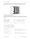
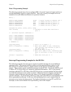
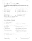
Mode 1 Output Programming Example
The following example shows how to configure PPI A for various combinations of mode 1
output. This code is strictly an example and is not intended to be used without modification in a
practical situation.
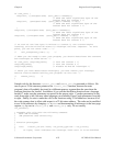
Main() {
#define BASE_ADDRESS 0x180 /* Board located at address 180 */
#define APORTAoffset 0x00 /* Offset for PPI A, port A */
#define APORTBoffset 0x01 /* Offset for PPI A, port B */
#define APORTCoffset 0x02 /* Offset for PPI A, port C */
#define ACNFGoffset 0x03 /* Offset for PPI A, CNFG */
unsigned int porta, portb, portc, cnfg;
char valread; /* Variable to store data read from a
port */
/* Calculate register addresses */
porta = BASE_ADDRESS + APORTAoffset;
portb = BASE_ADDRESS + APORTBoffset;
portc = BASE_ADDRESS + APORTCoffset;
cnfg = BASE_ADDRESS + ACNFGoffset;
/* EXAMPLE 1–port A output */