


Register-Level Programming Chapter 4
PC-DIO-96 User Manual 4-20 © National Instruments Corporation
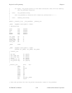
Main() {
#define BASE_ADDRESS 0x180 /* Board located at address 180 */
#define APORTAoffset 0x00 /* Offset for PPI A, port A */
#define APORTBoffset 0x01 /* Offset for PPI A, port B */
#define APORTCoffset 0x02 /* Offset for PPI A, port C */
#define ACNFGoffset 0x03 /* Offset for PPI A, CNFG */
#define IREG1offset 0x14 /* Offset for Interrupt Reg. 1 */
#define IREG2offset 0x15 /* Offset for Interrupt Reg. 2 */
unsigned int porta, portb, portc, cnfg, ireg1, ireg2;
char valread; /* Variable to store data read from a
port */
/* Calculate register addresses */
porta = BASE_ADDRESS + APORTAoffset;
portb = BASE_ADDRESS + APORTBoffset;
portc = BASE_ADDRESS + APORTCoffset;
cnfg = BASE_ADDRESS + ACNFGoffset;
ireg1 = BASE_ADDRESS + IREG1offset;
ireg2 = BASE_ADDRESS + IREG2offset;
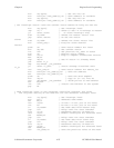
/* EXAMPLE 1–Set up interrupts for mode 1 input for port A. Enable the
appropriate interrupt bits. */
outp(cnfg,0xB0); /* Port A is an input in mode 1. */
outp(cnfg,0x09); /* Set PC4 to enable interrupts from
82C55A. */
outp(ireg1,0x01); /* Set AIRQ0 to enable PPI A, port A
interrupts. */
outp(ireg2,0x04); /* Set INTEN bit. */
/* EXAMPLE 2–Set up interrupts for mode 1 input for port B. Enable the
appropriate interrupt bits. */
outp(cnfg,0x86); /* Port B is an input in mode 1. */
outp(cnfg,0x05); /* Set PC2 to enable interrupts from
82C55A. */
outp(ireg1,0x02); /* Set AIRQ1 to enable PPI A, port B
interrupts. */
outp(ireg2,0x04); /* Set INTEN bit. */
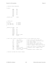
/* EXAMPLE 3–Set up interrupts for mode 1 output for port A. Enable the
appropriate interrupt bits. */
outp(cnfg,0xA0); /* Port A is an output in mode 1. */
outp(cnfg,0x0D); /* Set PC6 to enable interrupts from
82C55A. */
outp(ireg1,0x01); /* Set AIRQ0 to enable PPI A, port A
interrupts. */
outp(ireg2,0x04); /* Set INTEN bit. */
/* EXAMPLE 4–Set up interrupts for mode 1 output for port B. Enable the
appropriate interrupt bits. */