


Chapter 2 Configuration and Installation
© National Instruments Corporation 2-13 PC-DIO-96 User Manual
GND
PC-DIO-96 Board
Switch
I/O Connector
+5 V
+5 V
LED
TTL Signal
PPI A
Port A
APA<3..0>
PPI C
Port B
CPB<7..4>
41
43
45
47
67
71
73
69
50, 100
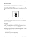
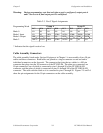
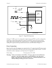
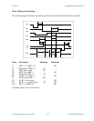
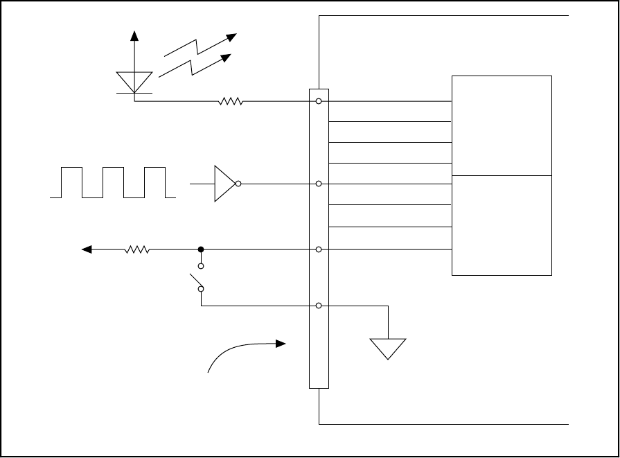
Figure 2-7. Digital I/O Connections
In Figure 2-7, PPI A, port A is configured for digital output, and PPI C, port B is configured for
digital input. Digital input applications include receiving TTL signals and sensing external
device states such as the state of the switch in Figure 2-7. Digital output applications include
sending TTL signals and driving external devices such as the LED shown in Figure 2-7.
Power Connections
Pins 49 and 99 of the I/O connector are connected to the +5 V supply from the PC power supply.
These pins are referenced to GND and can be used to power external digital circuitry. For more
information on these output pins, see Output Signals in Appendix A.
Power rating 0.5 A per pin at +5 V ± 10%
Warning: Under no circumstances should these +5-V power pins be connected directly to
ground or to any other voltage source on the PC-DIO-96 or any other device.
Doing so may damage the PC-DIO-96 and the PC. National Instruments is
NOT
liable for damage resulting from such a connection.