


Chapter 3 Theory of Operation
© National Instruments Corporation 3-3 PC-DIO-96 User Manual
handshaking circuitry; however, either of these two lines can be configured for input and used as
external interrupts. An interrupt occurs on the low-to-high transition of the signal line. Refer to
Chapter 4, Register-Level Programming, Appendix B, OKI 82C55A Data Sheet, or Appendix C,
AMD 8253 Data Sheet, for more detailed information.
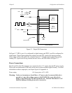
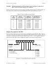
Digital I/O Connector
All digital I/O is transmitted through a standard, 100-pin, male connector. Pins 49 and 99 are
connected to +5 V through a protection fuse (F1). This +5 V supply is often required to operate
I/O module mounting racks. Pins 50 and 100 are connected to ground. See Chapter 2,
Configuration and Installation, for additional information.