


Register-Level Programming Chapter 4
PC-DIO-96 User Manual 4-4 © National Instruments Corporation
Warning: During programming, note that each time a port is configured, output ports A
and C are reset to 0, and output port B is undefined.
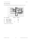
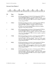
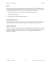
Table 4-2 shows the control words for setting or resetting each bit in port C. Notice that bit 7 of
the control word is cleared when programming the set/reset option for the bits of port C.
Table 4-2. Port C Set/Reset Control Words
Bit Bit Set Bit Reset The Bit Set or
Number Control Word Control Word Reset in Port C
0 0xxx0001 0xxx0000 xxxxxxxb
1 0xxx0011 0xxx0010 xxxxxxbx
2 0xxx0101 0xxx0100 xxxxxbxx
3 0xxx0111 0xxx0110 xxxxbxxx
4 0xxx1001 0xxx1000 xxxbxxxx
5 0xxx1011 0xxx1010 xxbxxxxx
6 0xxx1101 0xxx1100 xbxxxxxx
7 0xxx1111 0xxx1110 bxxxxxxx
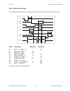
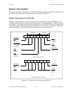
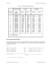
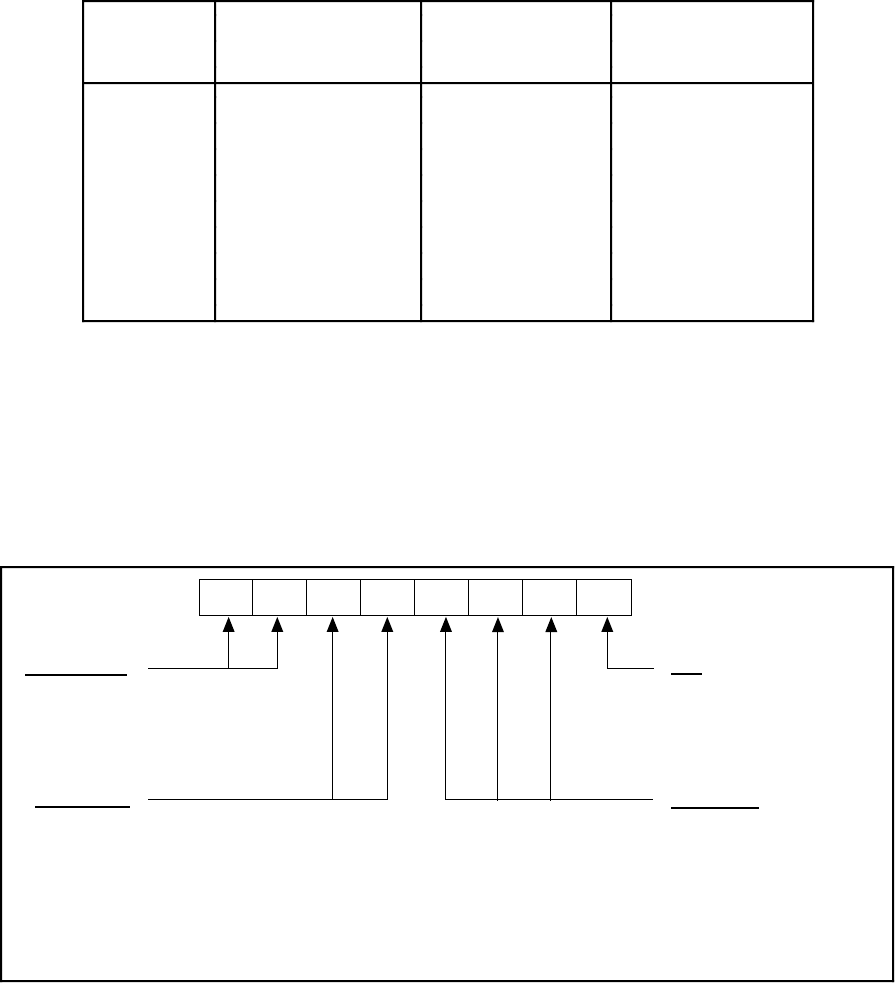
Register Description for the 8253
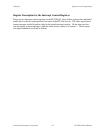
Figure 4-2 shows the control word format used to completely program the 8253. Bits 7 and 6 of
the control word select the counter to be programmed. Bits 5 and 4 select the mode by which the
count data is written to and read from the selected counter. Bits 3, 2, and 1 select the mode for
the selected counter. Bit 0 selects whether the counter counts in binary or BCD format.
BCD
D2 D1 D0D3D7
D6 D5
D4
1 = count in BCD
0 = count in binary
Mode Select
000 = mode 0
001 = mode 1
010 = mode 2
011 = mode 3
100 = mode 4
101 = mode 5
110 = mode 2
111 = mode 3
Access Mode
00 = latch counter value
01 = access LSB only
10 = access MSB only
11 = access LSB, then MSB
Counter Select
00 = counter 0
01 = counter 1
10 = counter 2
11 = illegal
Figure 4-2. Control-Word Format for the 8253