


Register-Level Programming Chapter 4
PC-DIO-96 User Manual 4-12 © National Instruments Corporation
porta = BASE_ADDRESS + APORTAoffset;
portb = BASE_ADDRESS + APORTBoffset;
portc = BASE_ADDRESS + APORTCoffset;
cnfg = BASE_ADDRESS + ACNFGoffset;
/* EXAMPLE 1*/
outp(cnfg,0x80); /* Ports A, B, and C are outputs. */
outp(porta,0x12); /* Write data to port A. */
outp(portb,0x34); /* Write data to port B. */
outp(portc,0x56); /* Write data to port C. */
/* EXAMPLE 2*/
outp(cnfg,0x90); /* Port A is input; ports B and C are
outputs. */
outp(portb,0x22); /* Write data to port B. */
outp(portc,0x55); /* Write data to port C. */
valread = inp(porta); /* Read data from port A. */
/* EXAMPLE 3 */
outp(cnfg,0x82); /* Ports A and C are outputs; port B
is an input. */
/* EXAMPLE 4 */
outp(cnfg,0x89); /* Ports A and B are outputs; port C
is an input. */
}
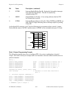
Mode 1—Strobed Input
In mode 1, the digital I/O bits are divided into two groups: group A and group B. Each of these
groups contains one 8-bit port and one 4-bit control/data port. The 8-bit port can be either an
input or an output port, and the 4-bit port is used for control and status information for the 8-bit
port. The transfer of data is synchronized by handshaking signals in the 4-bit port.
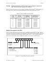
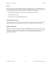
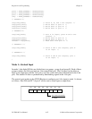
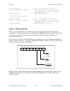
The control word written to the CNFG Register to configure port A for input in mode 1 is shown
as follows. Bits PC6 and PC7 of port C can be used as extra input or output lines.
D2 D1 D0D3D7
D6 D5
D4
1 = input
0 = output
Port C bits PC6 and PC7
1
0
1/0
X
X
X1 1