


Chapter 4 Register-Level Programming
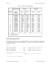
© National Instruments Corporation 4-15 PC-DIO-96 User Manual
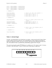
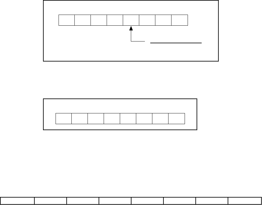
Mode 1—Strobed Output
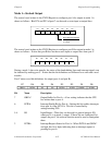
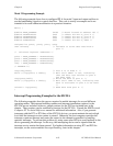
The control word written to the CNFG Register to configure port A for output in mode 1 is
shown as follows. Bits PC4 and PC5 of port C can be used as extra input or output lines.
D2 D1 D0D3D7
D6 D5
D4
1 = input
0 = output
Port C bits PC4 and PC5
1
0
1/0
X
X
X1 0
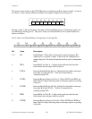
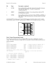
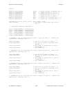
The control word written to the CNFG Register to configure port B for output in mode 1 is
shown as follows. Notice that port B does not have extra input or output lines from port C.
D2 D1 D0D3D7
D6 D5
D4
1
X
X
X 1 0 X
X
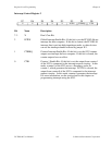
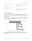
During a mode 1 data write transfer, the status of the handshaking lines and interrupt signals can
be obtained by reading port C. Notice that the bit definitions are different for a write and a read
transfer.
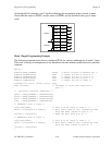
Port C status-word bit definitions for output (port A and port B):
D7 D6 D5 D4 D3 D2 D1 D0
OBFA* INTEA I/O I/O INTRA INTEB OBFB* INTRB
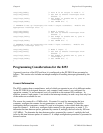
Bit Name Description
7 OBFA* Output Buffer for Port A—A low setting indicates that the CPU
has written data to port A.
6 INTEA Interrupt Enable Bit for Port A—Setting this bit enables interrupts
from port A of the 82C55A. This bit is controlled by
setting/resetting PC6.
5–4 I/O Input/Output—These bits can be used for general-purpose I/O
when port A is in mode 1 output. If these bits are configured for
output, the port C bit set/reset function must be used to manipulate
them.
3 INTRA Interrupt Request Status for Port A—When INTEA and OBFA*
are high, this bit is high, indicating that an interrupt request is
pending for port A.