


Chapter 2 Configuration and Installation
© National Instruments Corporation 2-17 PC-DIO-96 User Manual
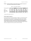
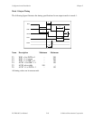
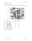
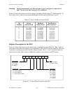
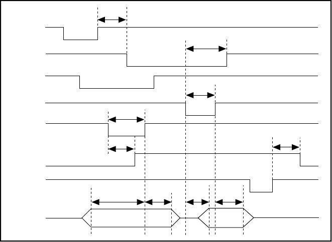
Mode 2 Bidirectional Timing
The following figure illustrates the timing specifications for bidirectional transfers in mode 2.
T2
T1
WR*
OBF*
INTR
ACK*
DATA
T6
T7
T3
T4
T10
STB*
T9
T8
T5
IBF
RD*
Name Description Minimum Maximum
T1 WR* = 1 to OBF* = 0 – 150
T2 Data before STB* = 1 20 –
T3 STB* pulse width 100 –
T4 STB* = 0 to IBF = 1 – 150
T5 Data after STB* = 1 50 –
T6 ACK* = 0 to OBF = 1 – 150
T7 ACK* pulse width 100 –
T8 ACK* = 0 to output – 150
T9 ACK* = 1 to output float 20 250
T10 RD* = 1 to IBF = 0 – 150
All timing values are in nanoseconds.