


Configuration and Installation Chapter 2
PC-DIO-96 User Manual 2-14 © National Instruments Corporation
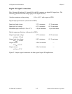
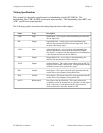
Timing Specifications
This section lists the timing specifications for handshaking with the PC-DIO-96. The
handshaking lines STB* and IBF synchronize input transfers. The handshaking lines OBF* and
ACK* synchronize output transfers.
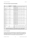
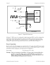
The following signals are used in the timing diagrams later in this chapter:
Name Type Description
STB* Input Strobe Input—A low signal on this handshaking line loads data
into the input latch.
IBF Output Input Buffer Full—A high signal on this handshaking line
indicates that data has been loaded into the input latch. This is
an input acknowledge signal.
ACK* Input Acknowledge Input—A low signal on this handshaking line
indicates that the data written to the port has been accepted.
This signal is a response from the external device indicating that
it has received the data from the PC-DIO-96.
OBF* Output Output Buffer Full—A low signal on this handshaking line
indicates that data has been written to the port.
INTR Output Interrupt Request—This signal becomes high when the 82C55A
requests service during a data transfer. The appropriate interrupt
enable bits must be set to generate this signal.
RD* Internal Read Signal—This signal is the read signal generated from the
control lines of the computer's I/O expansion bus.
WR* Internal Write Signal—This signal is the write signal generated from the
control lines of the computer's I/O expansion bus.
DATA Bidirectional Data Lines at the Specified Port—This signal indicates the
availability of data on the data lines at a port that is in the output
mode. If the port is in the input mode, this signal indicates
when the data on the data lines should be valid.