


Chapter 4 Register-Level Programming
© National Instruments Corporation 4-17 PC-DIO-96 User Manual
outp(cnfg,0xA0); /* Port A is an output in mode 1.*/
while (!(inp(portc) & 0x80)); /* Wait until OBFA* is set, indicating
that the data last written to port A
has been read.*/
outp(porta,0x12); /* Write data to port A. */
/* EXAMPLE 2–port B output */
outp(cnfg,0x84); /* Port B is an output in mode 1.*/
while (!(inp(portc) & 0x02)); /* Wait until OBFB* is set, indicating
that the data last written to port B
has been read.*/
outp(portb,0x34); /* Write the data to port B. */
}
Mode 2—Bidirectional Bus
Mode 2 has an 8-bit bus that can transfer both input and output data without changing the
configuration. The data transfers are synchronized with handshaking lines in port C. This mode
uses only port A; however, port B can be used in either mode 0 or mode 1 while port A is
configured for mode 2.
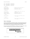
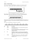
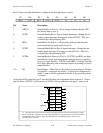
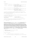
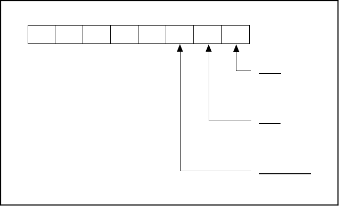
The control word written to the CNFG Register to configure port A as a bidirectional data bus in
mode 2 is shown as follows. If port B is configured for mode 0, then PC2, PC1, and PC0 of port
C can be used as extra input or output lines.
D2 D1 D0D3D7
D6 D5
D4
1 = input
0 = output
Port C
(PC2-PC0)
1
1/0
X
X
X1
1 = input
0 = output
Port B
0 = mode 0
1 = mode 1
Group B Mode
1/0
1/0
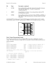
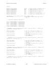
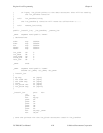
During a mode 2 data transfer, the status of the handshaking lines and interrupt signals can be
obtained by reading port C. The port C status-word bit definitions for a mode 2 transfer are
shown as follows.