


Chapter 4 Register-Level Programming
© National Instruments Corporation 4-3 PC-DIO-96 User Manual
Register Descriptions
The register descriptions for the devices on the PC-DIO-96, including the 82C55A, the 8253, and
each of the interrupt control registers, are given on the pages that follow.
Register Description for the 82C55A
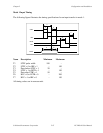
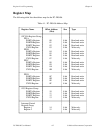
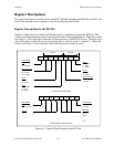
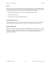
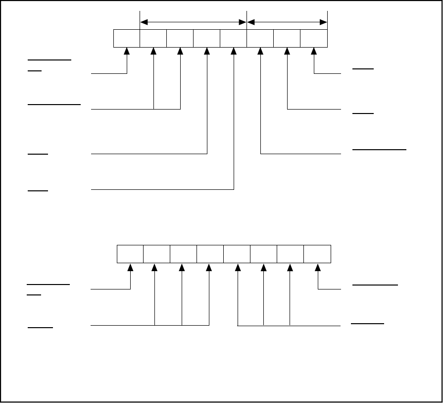
Figure 4-1 shows the two control word formats used to completely program the 82C55A. The
control word flag determines which control word format is being programmed. When the control
word flag is 1, bits 6 through 0 select the I/O characteristics of the 82C55A ports. These bits also
select the mode in which the ports are operating (that is, mode 0, mode 1, or mode 2). When the
control word flag is 0, bits 3 through 0 select the bit set/reset format of port C.
D2 D1 D0D5 D4 D3D7 D6
(high nibble)
1 = input
0 = output
Control Word
Flag
1 = mode set
00 = mode 0
01 = mode 1
1X = mode 2
Mode Selection
1 = input
0 = output
Port A
Port C
(low nibble)
1 = input
0 = output
Port C
0 = mode 0
1 = mode 1
Mode Selection
Group A Group B
Port B
1 = input
0 = output
Flag
D2 D1 D0D3D7
0 = bit set/reset
1 = set
0 = reset
(000)
(001)
(010)
:
:
(111)
Control Word
Bit Select
Bit Set/Reset
a. Mode Set Word Format
b. Bit Set/Reset Word Format
Unused
D6 D5
D4
Figure 4-1. Control Word Formats for the 82C55A