


Chapter 2 Configuration and Installation
© National Instruments Corporation 2-9 PC-DIO-96 User Manual
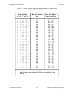
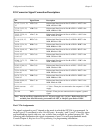
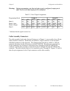
Warning: During programming, note that each time a port is configured, output ports A
and C are reset to 0, and output port B is undefined.
Table 2-3. Port C Signal Assignments
Programming Mode Group A Group B
PC7 PC6 PC5 PC4 PC3 PC2 PC1 PC0
Mode 0
I/O I/O I/O I/O I/O I/O I/O I/O
Mode 1 Input
I/O I/O IBF
A
STB
A
* INTR
A
STB
B
* IBFB
B
INTR
B
Mode 1 Output
OBF
A
* ACK
A
* I/O I/O INTR
A
ACK
B
* OBF
B
* INTR
B
Mode 2
OBF
A
* ACK
A
* IBF
A
STB
A
* INTR
A
I/O I/O I/O
* Indicates that the signal is active low.
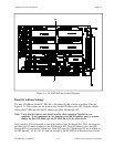
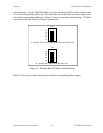
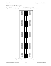
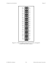
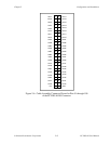
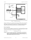
Cable Assembly Connectors
The cable assembly listed under Optional Equipment in Chapter 1 is an assembly of two 50-pin
cables and three connectors. Both cables are joined to a single connector on one end and to
individual connectors on the free ends. The connector that joins the two cables is a 100-pin
connector that plugs into the I/O connector of the PC-DIO-96. The other two connectors are
50-pin connectors, one of which is connected to pins 1 through 50 of the PC-DIO-96 I/O
connector, and the other of which is connected to pins 51 through 100 of the PC-DIO-96 I/O
connector. The cable with the label on it is connected to pins 1 through 50. Figures 2-5 and 2-6
show the pin assignments for the 50-pin connectors on the cable assembly.