Configuration and Installation Chapter 2
PC-DIO-96 User Manual 2-6 © National Instruments Corporation
4. Insert the PC-DIO-96 in an unused 8-bit, 16-bit, or 32-bit slot. It may be a tight fit, but do
not force the board into place.
5. Screw the mounting bracket of the PC-DIO-96 to the back panel rail of the computer.
6. Check the installation.
7. Replace the cover to the computer.
Note: If you have an ISA-class computer and you are using a configurable software package,
such as NI-DAQ, you may need to reconfigure your software to reflect any changes in
jumper or switch settings. If you have an EISA-class computer, you need to update the
computer's resource allocation (or configuration) table by reconfiguring your
computer. See your computer’s user manual for information about updating the
configuration table.
The PC-DIO-96 board is now installed and ready for operation.
Signal Connections
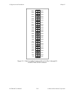
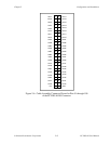
This section includes specifications and connection instructions for the signals given on the
PC -DIO-96 I/O connector.
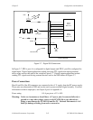
Warning: Connections that exceed any of the maximum ratings of input or output signals on
the PC-DIO-96 may result in damage to the PC-DIO-96 board and to the PC.
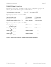
Maximum input ratings for each signal are given in this chapter under the
discussion of that signal. National Instruments is
NOT liable for any damages
resulting from any such signal connections.


