


Chapter 2 Configuration and Installation
© National Instruments Corporation 2-11 PC-DIO-96 User Manual
+5 V
CPA0
CPA1
CPA2
CPA3
CPA4
CPA5
CPA6
CPA7
CPB0
CPB1
CPB2
CPB3
CPB4
CPB5
CPB6
CPB7
CPC0
CPC1
CPC2
CPC3
CPC4
CPC5
CPC6
CPC7
GND
DPA1
DPA2
DPA4
DPA5
DPA6
DPA7
DPA0
DPA3
DPB0
DPB1
DPB2
DPB3
DPB4
DPB5
DPB6
DPB7
DPC0
DPC1
DPC2
DPC3
DPC4
DPC5
DPC6
DPC7
49 50
47 48
45 46
43 44
41 42
39 40
37 38
35 36
33 34
31 32
29 30
27 28
25 26
23 24
21 22
19 20
17 18
15 16
13 14
11 12
9 10
7 8
5 6
3 4
1 2
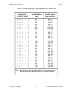
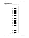
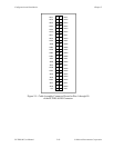
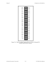
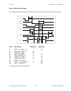
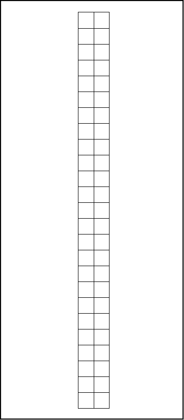
Figure 2-6. Cable-Assembly Connector Pinout for Pins 51 through 100
of the PC-DIO-96 I/O Connector