


Using the BayStack 410-24T 10BASE-T Switch
3-88
309985-A Rev 00
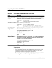
During the download process, the BayStack 410-24T switch is not operational.
You can monitor the progress of the download process by observing the LED
indications.
Table 3-33
describes the LED indications during the software download process.
Note: The LED indications described in Table 3-33 apply to a 24-port switch
model. Although a 12-port switch provides similar LED indications, the LED
indication sequence is associated within the 12-port range.
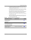
Table 3-33. LED Indications During the Software Download Process
Phase Description LED Indications
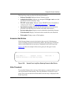
1 The switch downloads the new
software image.
Link status LEDs (ports 18 to 24 only):
The LEDs begin to
turn on in succession beginning with port 24, which indicates
the progress of the download process. When LEDs 18 to 24
are all on, the switch has received the new software image
successfully.
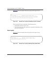
2 The switch erases the flash
memory.
Link status LEDs (ports 1 to 12 only):
The LEDs begin to
turn on in succession beginning with port 1, which indicates
that various sectors of the switch’s flash memory are being
erased. When LEDs 1 to 12 are all on, the switch’s flash
memory has been erased.
3 The switch programs the new
software image into the flash
memory.
Link status LEDs (ports 1 to 8 only):
The LEDs begin to
turn on in succession beginning with port 1, which indicates
that the new software image is being programmed into the
switch’s flash memory. When LEDs 1 to 8 are all on, the new
software image has been programmed successfully into the
switch’s flash memory.
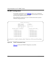
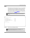
4 The switch resets automatically. After the reset completes, the new software image initiates
the switch’s self-test, which comprises various diagnostic
routines and subtests.
The LEDs display various patterns to indicate that the
subtests are in progress. The results of the self-test are
displayed briefly in the Self-Test screen, after which the CI
screens appear.