


Using the BayStack 410-24T 10BASE-T Switch
1-28
309985-A Rev 00
Stack Up Configurations
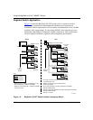
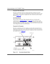
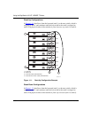
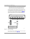
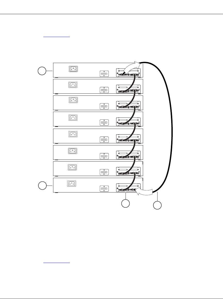
In Figure 1-11
, data flows from the base unit (unit 1) to the next switch, which is
assigned as unit 2, and continues until the last switch in the stack is assigned as
unit 8. The physical order of the switches is from bottom to top (unit 1 to unit 8).
Figure 1-11. Stack Up Configuration Example
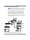
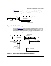
Stack Down Configurations
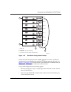
In Figure 1-12
, data flows from the base unit (unit 1) to the next switch, which is
assigned as unit 2, and continues until the last switch in the stack is assigned as
unit 8. The physical order of the switches is from top to bottom (unit 1 to unit 8).
Unit 7
Unit 8
1 = Last unit
2 = Base unit
3 = Cascade cable (PN 303978-A)
4 = Cascade max-return cable (PN 303979-A)
BS41011A
Unit 5
Unit 6
Unit 3
Unit 4
Unit 1
Unit 2
2
1
3
O
u
t
I
n
4