


Using the BayStack 410-24T 10BASE-T Switch
1-30
309985-A Rev 00
• You can downline upgrade the entire stack from any switch in the stack.
• You can access and manage the stack using a TELNET connection or any
generic SNMP management tool through any switch port that is part of the
stack configuration.
• When stacking three or more switches, use the longer (1-meter) cascade
max-return cable (PN 303979-A) to complete the link from the last unit in the
stack to the base unit.
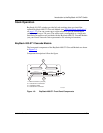
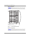
Redundant Cascade Stacking Feature
BayStack 410-24T Switches allow you to connect up to 8 units into a redundant
cascade stack. If any single unit fails or if a cable is accidently disconnected, other
units in the stack remain operational, without interruption.
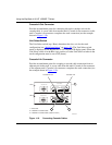
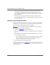
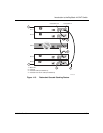
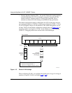
Figure 1-13
shows an example of how a stack configuration reacts to a failed or
powered-down unit in the stack configuration:
1.
As shown in Figure 1-13, unit 3 is not operational.
This can be the result of a failed unit, or simply because the unit was powered
down.
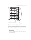
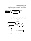
2.
Unit 2 and unit 4, directly upstream and downstream from unit 3, sense the
loss of link signals from unit 3.
• Unit 2 and unit 4 automatically loop their internal stack signals (A and B).
• The Cas Up LED for unit 2 and the Cas Dwn LED for unit 4 turn on
(amber) to indicate that the stack signals are looped.
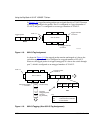
3.
The remaining stack units remain connected.
Although the example shown in Figure 1-13
shows a failed unit causing the stack
to loop signals at the points of failure (A and B), the system reacts the same way if
a cable is removed.