


Using the BayStack 410-24T 10BASE-T Switch
1-4
309985-A Rev 00
LED Display Panel
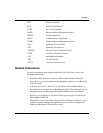
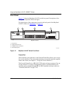
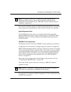
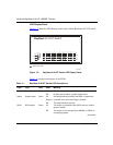
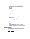
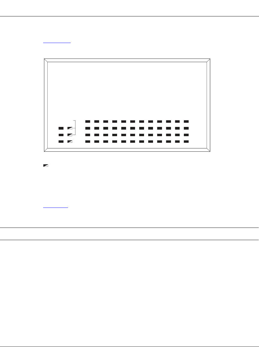
Figure 1-3
shows the LED display panels used with the BayStack 410-24T switch.
Figure 1-3. BayStack 410-24T Switch LED Display Panel
Table 1-1 provides descriptions of the LEDs.
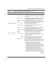
Table 1-1. BayStack 410-24T Switch LED Descriptions
Label Type Color State Meaning
Pwr Power status Green On DC power is available to the switch’s internal circuitry.
Off No AC power to switch, or power supply failed.
Status System status Green On Self-test passed successfully and switch is operational.
Blinking A nonfatal error occurred during the self-test.
Off The switch failed the self-test.
RPSU RPSU status Green On The switch is connected to the HRPSU and can receive
power if needed.
Off The switch is not connected to the HRPSU or HRPSU is
not supplying power.
(continued)
410-24T Switch
BayStack
Status
Dwn
Pwr Up
153
Cas
RPSUBase
Activity
Activity
2119 23
Link
Link
1713 151179
2642220 241814 1612810
BayStack 410-24T
BS41003A
= Dual color LED