


Using the BayStack 410-24T 10BASE-T Switch
1-58
309985-A Rev 00
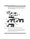
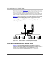
Each of the trunks shown in Figure 1-37 can be configured with up to four switch
ports to provide maximum aggregate bandwidth through each trunk, in full-duplex
mode. As shown in this example, when traffic between switch-to-switch
connections approaches single port bandwidth limitations, creating a MultiLink
Trunk can supply the additional bandwidth required to improve the performance.
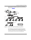
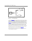
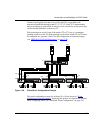
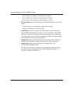
Figure 1-38
shows a typical switch-to-server trunk configuration. In this example,
file server FS1 uses dual MAC addresses, using one MAC address for each
network interface controller (NIC). For this reason, FS1 does not require a trunk
assignment. FS2 is a single MAC server (with a four-port NIC) and is set up as
trunk configuration T1.
Figure 1-38. Switch-to-Server Trunk Configuration Example
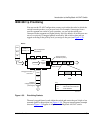
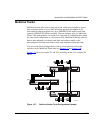
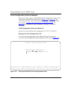
Client/Server Configuration Using MultiLink Trunks
Figure 1-39 shows an example of how MultiLink Trunking can be used in a
client/server configuration. In this example, both servers are connected directly to
switch S1. FS2 is connected through a trunk configuration (T1). The
switch-to-switch connections are through trunks (T2, T3, T4, and T5).
S1
FS1
FS2
T1
BS41032A