


Introduction to the BayStack 410-24T Switch
309985-A Rev 00
1-41
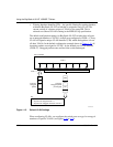
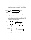
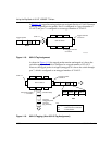
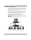
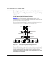
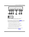
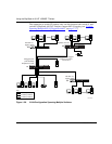
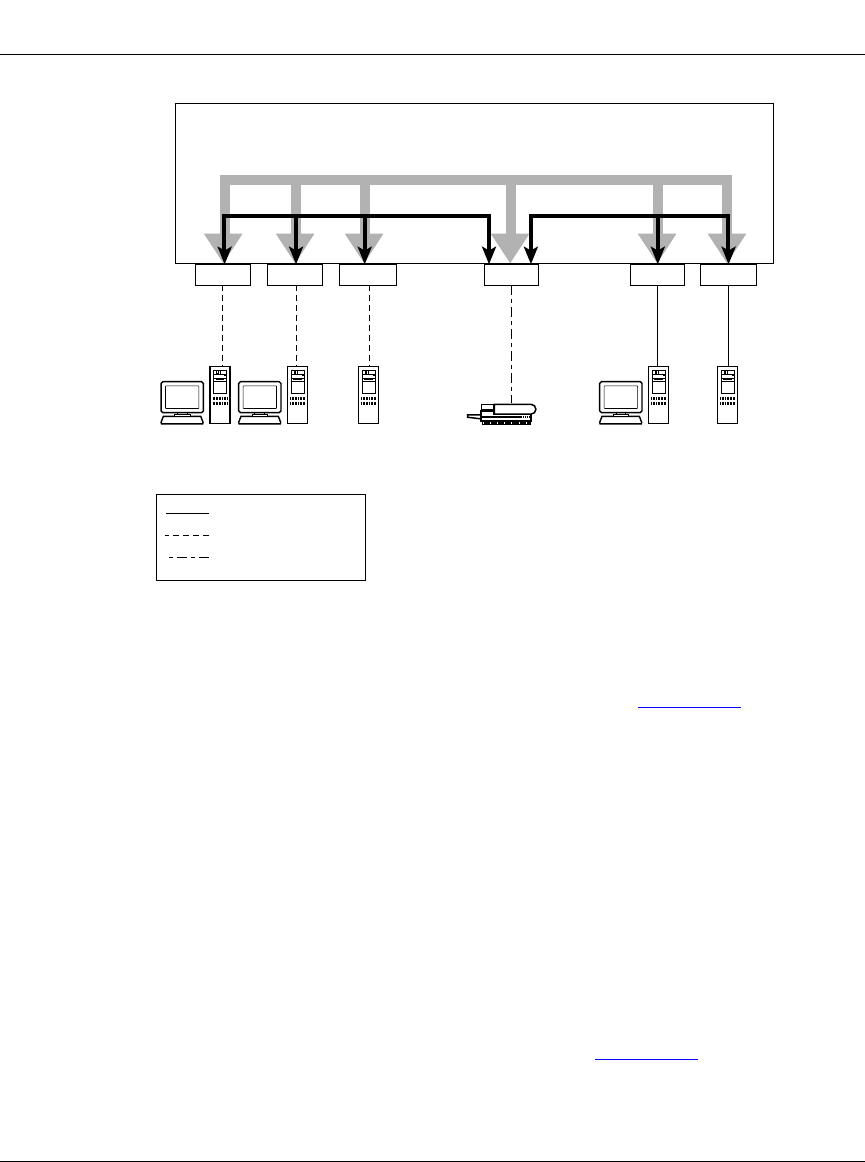
Figure 1-24. VLAN Broadcast Domains Within the Switch
The broadcast domain for each of the VLANs shown in Figure 1-24 is created by
configuring VLAN port memberships for each VLAN and then configuring each
of the ports with the appropriate PVID/VLAN association:
• Ports 8, 6, and 11 are untagged members of VLAN 1.
The PVID/VLAN association for ports 6 and 11 is: PVID = 1.
• Ports 2, 4, 10, and 8 are untagged members of VLAN 2.
The PVID/VLAN association for ports 2, 4, and 10 is: PVID = 2.
• Ports 2, 4, 10, 8, 6, and 11 are untagged members of VLAN 3.
The PVID/VLAN association for port 8 is: PVID = 3.
The following steps show how to use the VLAN configuration screens to
configure the VLAN 3 broadcast domain shown in Figure 1-24
.
Port 2
BS41024A
Port 4 Port 10 Port 8
VLAN 3
V2 V2 V2 V1 V2
VLAN 2 VLAN 1
S1
Key
VLAN 1 (PVID = 1)
VLAN 2 (PVID = 2)
VLAN 3 (PVID = 3)
PVID = 2 PVID = 3
V3
PVID = 1
Port 11Port 6