


Using the BayStack 410-24T 10BASE-T Switch
1-2
309985-A Rev 00
Front Panel
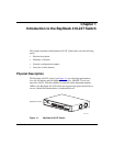
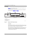
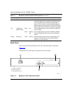
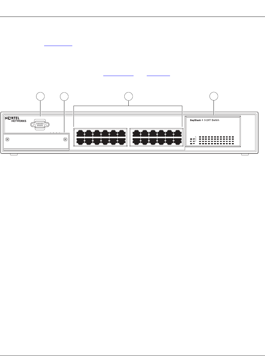
Figure 1-2 shows the BayStack 410-24T switch front panel. Descriptions of the
front panel components follow the figure.
For a description of the components located on the back panel of the BayStack
410-24T switch, see “Back Panel
” on page 1-6.
Figure 1-2. BayStack 410-24T Switch Front Panel
Comm Port
The Comm Port (also referred to as the Console/Comm Port) allows you to access
the console interface (CI) screens and customize your network using the supplied
menus and screens (see Chapter 3, “Using the Console Interface”).
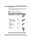
The Console/Comm Port is a DB-9, RS-232-D male serial port connector. You can
use this connector to connect a management station or console/terminal to the
switch by using a straight-through DB-9 to DB-9 standard serial port cable (see
“Console/Comm Port” on page 2-10).
Uplink/Expansion Module
2826 2725
Comm Port
17 1913 15 21
18 2014 16 22 24
23
Status
Dwn
Pwr Up
Cas
RPSU Base
Activity
Activity
Link
Link
1
2
3
4
BayStack 410-24T
1
2
3
4
= Comm Port
= Uplink/Expansion slot
= 10BASE-T port connectors
= LED display panel
BS41002A
5713 9
682 4 10 12
11
1