


Web OS 10.0 Application Guide
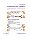
Chapter 6: Server Load Balancing
125
212777-A, February 2002
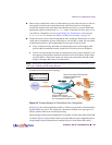
2. Define an IP interface on the switch.
The switch must have an IP route to all of the real servers that receive Web switching services.
For SLB, the switch uses this path to determine the level of TCP/IP reach of the real servers.
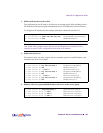
To configure an IP interface for this example, enter these commands from the CLI:
NOTE – The IP interface and the real servers must belong to the same VLAN, if they are in the
same subnet. This example assumes that all ports and IP interfaces use default VLAN 1,
requiring no special VLAN configuration for the ports or IP interface.
3. Define each real server.
For each real server, you must assign a real server number, specify its actual IP address, and
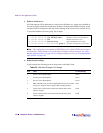
enable the real server. For example:
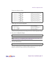
4. Define a real server group and add the three real servers to the service group.
>> # /cfg/ip/if 1 (Select IP interface 1)
>> IP Interface 1# addr 200.200.200.100 (Assign IP address for the interface)
>> IP Interface 1# ena (Enable IP interface 1)
>> IP Interface 1# /cfg/slb/real 1 (Server A is real server 1)
>> Real server 1# rip 200.200.200.2 (Assign Server A IP address)
>> Real server 1# ena (Enable real server 1)
>> Real server 1# ../real 2 (Server B is real server 2)
>> Real server 2# rip 200.200.200.3 (Assign Server B IP address)
>> Real server 2# ena (Enable real server 2)
>> Real server 2# ../real 3 (Server C is real server 3)
>> Real server 3# rip 200.200.200.4 (Assign Server C IP address)
>> Real server 3# ena (Enable real server 3)
>> Real server 3# /cfg/slb/group 1 (Select real server group 1)
>> Real server group 1# add 1 (Add real server 1 to group 1)
>> Real server group 1# add 2 (Add real server 2 to group 1)
>> Real server group 1# add 3 (Add real server 3 to group 1)