


Web OS 10.0 Application Guide
140
Chapter 6: Server Load Balancing
212777-A, February 2002
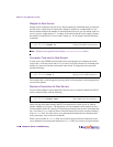
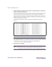
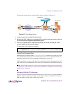
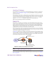
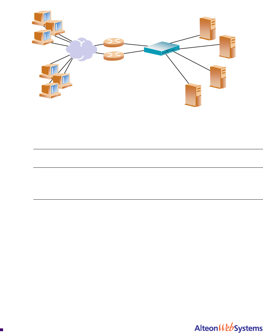
Consider the following network:
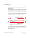
Figure 6-6 Basic Virtual Port to Real Port Mapping Configuration
In this example, four real servers are used to support a single service (HTTP). Clients access
this service through a virtual server with IP address 192.168.2.100 on virtual port 80. Since
each real server uses two ports (8001 and 8002) for HTTP services, the logical real servers are:
n 192.168.2.1/8001
n 192.168.2.1/8002
n 192.168.2.2/8001
n 192.168.2.2/8002
n 192.168.2.3/8001
n 192.168.2.3/8002
n 192.168.2.4/8001
n 192.168.2.4/8002
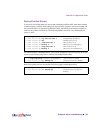
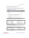
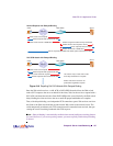
Domain Name virtual server IP
address
Ports Activated Port Mapping Real Server IP
Address
www.right.com 192.168.2.100 80 (HTTP) 8001 (rport 1)
8002 (rport 2)
192.168.2.1 (RIP 1)
192.168.2.2 (RIP 2)
192.168.2.3 (RIP 3)
192.168.2.4 (RIP 4)
Real Servers
Web Switch
Web Clients
Internet
Web Host
Routers
192.168.2.1
192.168.2.2
192.168.2.3
192.168.2.4
8001
8002
8001
8002
8001
8002
8001
8002