


Web OS 10.0 Application Guide
30
Chapter 1: Basic IP Routing
212777-A, February 2002
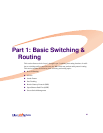
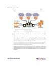
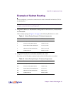
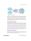
Take a closer look at the Alteon Web switch in the following configuration example:
Figure 1-2 Switch-Based Routing Topology
The Alteon Web switch connects the Gigabit Ethernet and Fast Ethernet trunks from various
switched subnets throughout one building. Common servers are placed on another subnet
attached to the switch. A primary and backup router are attached to the switch on yet another
subnet.
Without Layer 3 IP routing on the switch, cross-subnet communication is relayed to the default
gateway (in this case, the router) for the next level of routing intelligence. The router fills in the
necessary address information and sends the data back to the switch, which then relays the
packet to the proper destination subnet using Layer 2 switching.
With Layer 3 IP routing in place on the Alteon Web switch, routing between different IP sub-
nets can be accomplished entirely within the switch. This leaves the routers free to handle
inbound and outbound traffic for this group of subnets.
To make implementation even easier, UDP Jumbo frame traffic is automatically fragmented to
regular Ethernet frame sizes when routing to non-Jumbo frame VLANS or subnets. This auto-
matic frame conversion allows servers to communicate using Jumbo frames, all transparently
to the user.
Third Floor
10/100 Client Subnet
208.31.177.1-254
Second Floor
10/100 Client Subnet
131.15.15.1-254
First Floor
10/100 Client Subnet
100.20.10.1-254
1000 Mbps
1000 Mbps
1000 Mbps
Alteon Web Switch
Secondary Default
Router: 205.21.17.2
Server Subnet:
206.30.15.1-254
Primary Default
Router: 205.21.17.1
IF#1 IF#5
IF#3
IF#2 IF#4
IP Routing